ALLPCB


Electromagnetic interference continues to challenge the performance and reliability of electronic systems across industries. Engineers must address noise sources that can disrupt signal integrity, cause malfunctions, or lead to regulatory non-compliance. Inductors serve as fundamental components in EMI filters because they present high impedance to alternating current noise while permitting direct current to flow with minimal loss. Effective EMI filter inductor selection therefore forms a critical step in circuit design. This guide examines the engineering considerations that guide proper inductor choice for noise reduction applications.
Why Inductor Selection Matters for EMI Filtering
In dense electronic assemblies, conducted and radiated emissions can couple into power lines and signal paths, degrading overall system performance. An inductor chosen without regard for operating frequency, current levels, and parasitic elements may fail to suppress noise adequately or may introduce excessive voltage drop. Proper inductor for noise reduction helps meet electromagnetic compatibility requirements while maintaining power efficiency. Engineers evaluate inductor characteristics for emi early in the design cycle to avoid costly board revisions later. Systematic selection also supports long-term product reliability under varying environmental conditions.
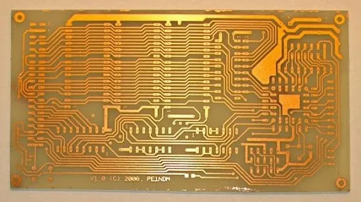
Industry standards such as those outlined in IPC-6012E emphasize the need for robust component integration on printed boards to maintain electrical performance.
Technical Principles of Inductors in EMI Suppression
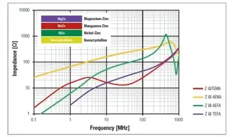
An inductor opposes changes in current through the generation of a magnetic field, creating an impedance that rises with frequency. In EMI filters this property attenuates high-frequency noise while the low DC resistance allows steady-state power delivery. Core materials determine the inductor's behavior: ferrite cores offer high permeability at lower frequencies, whereas powdered iron or alloy cores provide better saturation characteristics at higher currents. Parasitic capacitance between windings creates a self-resonant frequency beyond which the component behaves capacitively rather than inductively. Shielded constructions reduce magnetic field leakage that could couple into adjacent traces or components on the board.
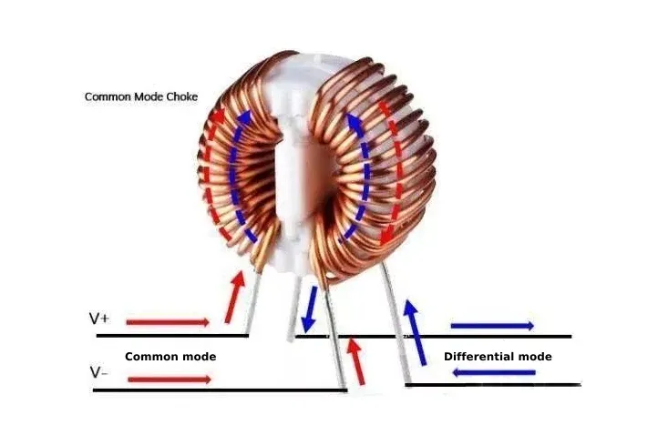
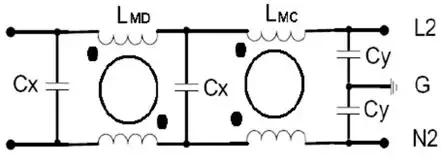
Engineers must also consider temperature effects on core permeability and winding resistance, as these factors shift impedance over the operating range. Differential-mode and common-mode noise require distinct inductor configurations, with the latter often employing coupled windings on a single core. Understanding these mechanisms enables precise placement of the inductor within LC or pi-filter topologies for optimal attenuation.
Key Inductor Characteristics for EMI Applications
Inductance value must match the target noise frequency band to achieve the desired impedance. Current ratings, both saturation and RMS, ensure the core does not saturate under peak loads and that thermal rise remains within acceptable limits. DC resistance directly affects efficiency and heat generation in the filter stage. Self-resonant frequency should lie well above the highest noise frequency of interest to maintain inductive behavior. Package size, mounting style, and shielding effectiveness influence both electrical performance and mechanical integration on the printed circuit board.
Additional parameters include quality factor at the operating frequency and tolerance on inductance, which together affect filter response consistency across production units. Engineers compare these characteristics against the specific EMI spectrum measured in the application to narrow options systematically.
Best Practices in EMI Filter Inductor Selection
Begin by characterizing the noise spectrum through measurement or simulation to identify dominant frequencies and amplitudes. Select inductance that provides sufficient impedance at those frequencies while respecting the available board space and current requirements. Verify that the chosen part maintains performance across the full temperature and current range expected in operation. Consider layout factors such as trace routing, ground plane proximity, and separation from sensitive circuits to minimize unintended coupling.
When multiple inductors appear in a filter, ensure their self-resonant frequencies do not interact to create unwanted resonances. Prototype testing under realistic load and environmental conditions validates the selection before committing to volume production. Documentation of the decision process supports traceability and future design reviews.
Standards such as ISO 9001:2015 highlight the importance of controlled design and verification processes that include component selection for electromagnetic performance.
Practical Integration Considerations on PCBs
Component placement should minimize loop areas that could radiate or pick up noise. Thermal management through adequate copper area or vias helps control temperature rise in high-current paths. Mechanical stress from board flexure or vibration must be evaluated, particularly for larger through-hole inductors. When surface-mount parts are selected, solder joint reliability under thermal cycling becomes an additional factor.
Engineers often iterate between simulation and measurement to refine the inductor choice and surrounding circuitry. This structured approach reduces the risk of late-stage compliance failures.
Conclusion
Selecting an inductor for EMI filtering requires balancing electrical parameters, physical constraints, and system-level requirements. A methodical evaluation of inductance, current handling, frequency response, and integration factors leads to effective noise reduction. Adherence to established engineering practices and relevant industry standards supports consistent, reliable outcomes across designs. Engineers who apply these principles achieve better electromagnetic compatibility with fewer design iterations.
FAQs
Q1: What factors drive EMI filter inductor selection in power circuits?
A1: Engineers evaluate inductance value, saturation current, DC resistance, and self-resonant frequency against the measured noise spectrum and operating conditions. Additional considerations include core material behavior, shielding effectiveness, and thermal performance to ensure stable noise reduction without excessive power loss or board space usage.
Q2: How do inductor characteristics for emi influence filter effectiveness?
A2: Inductor characteristics for emi such as impedance profile, parasitic elements, and current ratings determine how well unwanted signals are attenuated while desired power flows unimpeded. Proper matching of these traits to the application frequency and load prevents both under-filtering and unintended resonances.
Q3: Why is inductor for noise reduction critical during PCB layout?
A3: An inductor for noise reduction placed without regard for trace routing or proximity to other components may couple noise elsewhere or suffer from increased parasitic effects. Careful selection combined with thoughtful layout maximizes attenuation and maintains signal integrity throughout the assembly.
Q4: What steps ensure reliable performance after EMI filter inductor selection?
A4: Verification through prototype testing under actual operating temperatures, currents, and load variations confirms that the chosen inductor maintains its intended impedance and thermal characteristics. Documentation of measurements and any adjustments supports ongoing compliance and future design reuse.
References
IPC-6012E — Qualification and Performance Specification for Rigid Printed Boards. IPC, 2017
ISO 9001:2015 — Quality Management Systems. ISO, 2015
JEDEC J-STD-020E — Moisture/Reflow Sensitivity Classification. JEDEC, 2014