ALLPCB


Introduction
Electronic hobbyists building audio amplifiers and speakers often face the shift to lead-free solder due to environmental regulations and health concerns. While traditional tin-lead solders offered easy flow and reliable joints, lead-free alternatives demand careful selection and technique to preserve signal quality and fidelity. Poor solder joints can introduce distortion, alter impedance, and degrade audio performance, making the choice critical for high-fidelity setups. This article explores the best lead-free solder options for audio applications, focusing on alloys that minimize lead-free solder distortion and maintain lead-free solder impedance. By understanding technical principles and best practices, hobbyists can achieve joints comparable to legacy solders. With proper implementation, lead-free solder audio quality remains uncompromised in amplifiers and speakers.
Why Lead-Free Solder Matters in Audio Applications
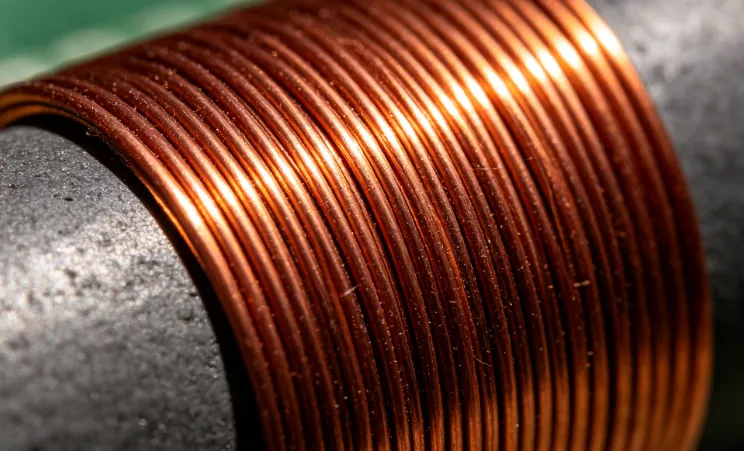
Lead-free solder became standard following directives like RoHS, pushing hobbyists to adapt for sustainable builds. In audio circuits, where signal paths carry delicate waveforms, solder joints form the backbone of conductivity and mechanical stability. Subpar joints from mismatched alloys or improper soldering can lead to micro-cracks under vibration, common in speakers, resulting in intermittent contact and noise. For amplifiers, consistent impedance matching prevents reflections that cause lead-free solder distortion. Hobbyists must prioritize alloys with good wetting and ductility to avoid these pitfalls. Ultimately, selecting the right lead-free solder for amplifiers and speakers ensures long-term reliability without sacrificing sound clarity.
Audio enthusiasts report challenges with lead-free solders, such as higher melting points complicating hand soldering. These solders typically require temperatures 30 to 50 degrees Celsius higher than tin-lead, risking component damage if uncontrolled. Yet, modern alloys bridge this gap, offering flow properties suitable for point-to-point wiring in tube amps or SMD work on class-D modules. Vibration sensitivity in speaker crossovers amplifies joint reliability needs, where brittle intermetallics could introduce triboelectric noise. By focusing on solder composition, hobbyists mitigate lead-free solder impedance mismatches that skew frequency response. This relevance underscores why targeted selection elevates DIY audio projects.
Technical Principles Behind Lead-Free Solder Performance in Audio
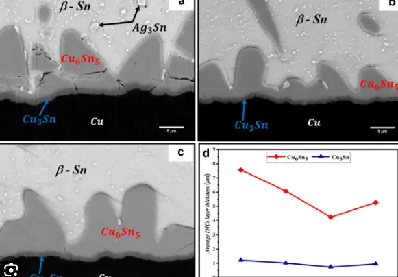
Lead-free solders primarily consist of tin-silver-copper (SAC) alloys, where silver enhances strength and copper improves wetting on copper pads. During reflow or hand soldering, tin forms an intermetallic compound (IMC) layer with the PCB copper, crucial for joint integrity but prone to excessive growth in lead-free systems. Thick IMCs reduce ductility, making joints vulnerable to thermal cycling in power amplifiers, potentially causing fatigue cracks that manifest as lead-free solder distortion. Signal fidelity depends on low joint resistance, typically below milliohms, to prevent voltage drops across high-current paths in speaker outputs. Impedance consistency along traces avoids mismatches, preserving waveform shape up to 20 kHz and beyond.
J-STD-001 outlines criteria for acceptable lead-free joints, including minimum fillet heights and void limits under 25 percent for reliable conductivity. In audio paths, voids trap flux residues that corrode over time, increasing capacitance and introducing phase shifts. Electromigration in high-silver alloys accelerates under bias in class-AB amps, subtly altering lead-free solder audio quality through resistance creep. Lower-silver SAC variants balance this by reducing brittleness while maintaining creep resistance. Vibration in speakers induces microphonics if joints lack compliance, converting mechanical energy to electrical noise. Understanding these mechanisms guides alloy choice for distortion-free performance.
Thermal expansion mismatch between solder and components further influences reliability. Lead-free solders exhibit higher Young's modulus, transmitting vibrations more efficiently to sensitive op-amps in preamps. Proper flux activation ensures complete wetting, minimizing dewetting that raises contact resistance and harmonic distortion. Alloy microstructure post-solidification determines long-term stability, with refined grains resisting grain boundary sliding. For hobbyists, these principles translate to selecting SAC305-like compositions, known for robust audio signal paths.
Best Lead-Free Solder Alloys for Audio Applications
SAC305, with approximately 96.5 percent tin, 3 percent silver, and 0.5 percent copper, stands out for audio due to its balanced properties. This eutectic-near alloy melts around 217 degrees Celsius, allowing hand soldering without excessive heat soak on temperature-sensitive parts. Its silver content provides shear strength for speaker driver connections under excursion forces, reducing lead-free solder distortion from mechanical stress. Compared to pure tin-copper, SAC305 offers superior creep resistance, vital for amplifiers handling dynamic loads. Hobbyists favor it for consistent impedance in RF-sensitive crossover networks.
Lower-silver options like SAC0807 minimize electromigration while improving ductility for vibration-prone areas. These alloys exhibit better shock resistance per drop tests adapted from electronics standards, translating to fewer failures in portable speaker builds. Tin-copper-nickel variants enhance wetting on oxidized pads common in vintage audio mods. Avoid high-bismuth alloys, as they embrittle rapidly under thermal stress. For lead-free solder for speakers, prioritize alloys with 0.5 to 1 percent copper to match PCB finish reactivity.
Particle size in solder paste for reflow affects voiding in dense amp layouts. Finer powders yield smoother joints, preserving lead-free solder impedance uniformity. Flux no-clean types prevent ionic contamination that boosts noise floors in phono stages. Alloy selection hinges on application: higher silver for static amp boards, lower for flexing speaker wires.
Practical Solutions and Best Practices for Soldering Audio Circuits
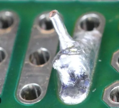
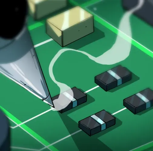
Start with a temperature-controlled iron set 50 degrees above alloy melt point, typically 350 degrees Celsius for SAC, using fine tips for precision. Clean components and boards with isopropyl alcohol to ensure flux efficacy, preventing cold joints that spike distortion. Apply flux sparingly to pads and leads, heating from board side to avoid lift-off in through-hole speaker terminals. Dwell time of 2 to 3 seconds promotes IMC formation without excess, aligning with J-STD-001 guidelines. Inspect for concave fillets and shine, indicators of void-free bonds.
IPC-A-610 acceptability classes guide visual checks: Class 3 for high-reliability audio demands no cracks or dewetting. Post-solder cleaning removes residues, especially in humid environments where corrosion erodes signal quality. For lead-free solder for amplifiers, use drag soldering on ICs to minimize bridges. Vibration testing via gentle tapping verifies mechanical stability in speaker prototypes.
Troubleshoot distortion by reflowing suspect joints, often culprits in intermittent hum. Measure joint resistance under load; deviations signal IMC issues. Preheat boards for SMD reflow in class-D amps to control ramp rates. Store solder in dry conditions to prevent tin whisker growth, a rare but real impedance disruptor.
Troubleshooting Common Issues in Audio Builds
Hobbyists frequently encounter brittle joints cracking in speaker cabinets from cone movement. Solution: reinforce with conformal coating or select ductile low-Ag alloys, reflowing per IPC-A-610 criteria. Distortion spikes post-assembly trace to flux activation failures; rebake boards at 125 degrees Celsius for 24 hours before rework. Impedance mismatches appear as high-frequency roll-off; verify trace continuity with TDR if available, or substitute suspect joints.
Microphonics in tube amps stem from loose lead-free connections; secure with mechanical strain relief. Overheated components show discoloration; dial back dwell and use thermal profiling. These fixes restore lead-free solder audio quality without full rebuilds.
Conclusion
Choosing the right lead-free solder alloy like SAC305, combined with precise techniques, ensures audio circuits deliver pristine signal fidelity. By addressing distortion risks, impedance stability, and vibration resilience, hobbyists achieve professional results. Adhering to standards like J-STD-001 elevates DIY amplifiers and speakers. Transition confidently, prioritizing joint quality for enduring performance.
FAQs
Q1: What impact does lead-free solder have on audio quality in amplifiers?
A1: Lead-free solder maintains audio quality when joints meet J-STD-001 criteria, avoiding voids that increase resistance and cause distortion. SAC alloys provide low contact resistance, preserving signal integrity in high-gain stages. Poor wetting leads to higher noise floors, but proper flux and temperature control mitigate this. Hobbyists report comparable fidelity to leaded solders with practice.
Q2: How does lead-free solder affect distortion in speaker crossovers?
A2: In speakers, lead-free solder distortion arises from micro-cracks under vibration if alloys lack ductility. Low-Ag SAC variants resist fatigue better, maintaining impedance matching for flat response. Inspect per IPC-A-610 for fillet integrity post-assembly. Flux residues amplify issues, so clean thoroughly. This ensures clean bass and treble without harmonic artifacts.
Q3: Can lead-free solder maintain impedance in audio signal paths?
A3: Yes, lead-free solder impedance stays consistent with good wetting, preventing reflections in traces. SAC305 excels here, forming stable IMCs that match copper traces. Avoid cold joints via adequate preheat. For amplifiers, this preserves phase coherence up to 20 kHz. Vibration testing confirms long-term stability.
Q4: What is the best lead-free solder for amplifiers and speakers?
A4: SAC305 balances strength, flow, and reliability for both amplifiers and speakers. It handles thermal loads in amps and mechanical stress in speakers without excess brittleness. Use no-clean flux for clean joints. Follow J-STD-001 for verification. This alloy minimizes distortion while easing hand soldering.
References
J-STD-001G — Requirements for Soldered Electrical and Electronic Assemblies. IPC, 2017
IPC-A-610H — Acceptability of Electronic Assemblies. IPC, 2019
IPC J-STD-006C — Requirements for Electronic Grade Solder Alloys and Fluxed and Non-Fluxed Solders. IPC, 2010