 ALLPCB


Introduction
Solder paste serves as the cornerstone of surface mount technology assembly, particularly in reflow soldering processes for printed circuit boards. This grey, creamy material combines microscopic solder particles with flux to form reliable electrical and mechanical joints between components and pads. Electric engineers rely on precise solder paste selection and application to minimize defects like bridging, voids, or insufficient solder volume. Understanding solder paste types, composition, and handling directly impacts yield rates and long-term reliability in high-volume production. This guide delves into practical aspects, from composition to troubleshooting, equipping you with actionable insights for optimal reflow outcomes. 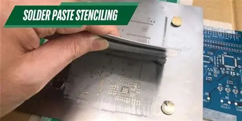
What Is Solder Paste and Why Does It Matter in Reflow Soldering?
Solder paste is a homogeneous mixture of solder alloy powder suspended in a flux medium, designed to deposit controlled amounts of solder onto PCB pads during stencil printing. In reflow soldering, the paste undergoes preheat, activation, reflow, and cooling phases, where flux cleans surfaces, solder melts, and forms intermetallic bonds. Poor solder paste performance leads to common issues like tombstoning, where components lift due to uneven reflow, or solder beading, excess material that shorts adjacent pads. Engineers must prioritize solder paste because it influences voiding, which can trap heat and accelerate failures in power electronics. Consistent paste behavior ensures compliance with assembly standards and supports miniaturization trends in fine-pitch devices. Proper management prevents costly rework and maintains signal integrity in high-frequency applications.
Solder Paste Composition: The Building Blocks
Solder paste typically consists of 85 to 92 percent solder alloy powder by weight, with the remainder being flux vehicle. The powder derives from alloys like tin-lead or lead-free variants such as tin-silver-copper, providing the conductive material that melts during reflow. Flux includes activators to remove oxides, solvents for viscosity control, rosins for protection, and thixotropic agents that prevent slumping while allowing shear-thinning during printing. This balance ensures the paste releases volatiles cleanly without leaving corrosive residues. Variations in composition affect reflow profiles, with lead-free pastes requiring higher peak temperatures to achieve wetting. Troubleshooting composition mismatches often reveals root causes for incomplete coalescence or excessive flux entrapment.
Solder Paste Types: Matching to Your Assembly Needs
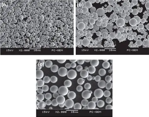
Solder paste types classify primarily by particle size and flux chemistry, with IPC defining powder categories from Type 3 to Type 5 for reflow applications. Type 3 paste features particles of 25 to 45 micrometers, suitable for standard pitches above 0.5 mm where robustness trumps ultra-fine deposition. Finer Type 4 (20 to 38 micrometers) and Type 5 (15 to 25 micrometers) excel in high-density boards, reducing bridging on 0.3 mm or smaller pitches but demanding precise stencil control. Flux types include no-clean for residue-free post-reflow cleaning, water-soluble for aggressive activation in dirty environments, and rosin-based for traditional processes. Lead-free types dominate due to regulations, while low-temperature variants ease thermal stress on sensitive components. Selecting the wrong type often manifests as print defects, so test for your specific reflow oven and board finish.
Solder Paste Selection: Key Criteria for Electric Engineers
Solder paste selection hinges on alloy compatibility with reflow profiles, particle size for feature density, and flux activity for pad finishes like ENIG or HASL. Evaluate metal loading, typically 85 to 90 percent, to ensure sufficient volume post-reflow without excess. Consider viscosity, measured in centipoise, which affects release from stencil apertures; higher for fine features prevents bridging. Environmental factors like humidity influence flux stability, favoring no-clean for controlled factories. Always validate against IPC J-STD-001 requirements for soldered assemblies to avoid reliability risks. Practical testing, including slump and solder ball tests, confirms performance before full production runs.
Solder Paste Application: Mastering Stencil Printing
Stencil printing deposits solder paste accurately, with parameters like aperture ratio, print speed (20 to 100 mm per second), and squeegee pressure (1 to 10 kg) dictating deposit quality. Use stainless steel or nickel stencils at 100 to 125 micrometers thick for Type 4 paste, ensuring 75 percent paste-in-hole transfer efficiency. Snap-off distance of 1 to 2 mm prevents smearing, while controlled humidity (40 to 60 percent RH) maintains rheology. Inspect prints with SPI for volume uniformity, addressing skips via gasketing or under-stencil cleaning. Double-printing techniques boost volume for large pads without reflow adjustments. Per IPC-7525 guidelines, optimize these for consistent reflow joints, troubleshooting low transfer as stencil wear or paste drying.

Solder Paste Storage and Shelf Life: Preventing Performance Degradation
Proper solder paste storage extends usability, with refrigeration at 2 to 10 degrees Celsius yielding a shelf life of three to six months unopened. Room temperature storage shortens this to one month maximum, as solvents evaporate and viscosity thickens. After opening, use within one to four weeks, rolling the jar 30 minutes before printing to remix settled powder. Avoid refreezing, as it causes separation; thaw naturally over four hours to prevent condensation. Monitor for signs of degradation like graining or separation, discarding if present. These practices align with handling protocols to sustain stencil printing consistency and reflow yields.
Best Practices and Troubleshooting for Reflow Success
Roll paste before each use to homogenize, and maintain printer environment at 22 to 26 degrees Celsius with low humidity. Implement under-stencil wipe every 5 to 10 prints, using lint-free materials to avoid scratches. For reflow, preheat slowly to activate flux without rapid solvent boil-off, targeting peak temperatures per alloy specs. Troubleshoot voids by increasing metal load or adjusting soak time; bridging responds to finer powder or reduced squeegee speed. Profile ovens regularly per IPC J-STD-001 to correlate paste behavior with thermal ramps. Document trials to refine processes, reducing defects from 2 percent to under 0.5 percent in mature lines.
Common pitfalls include inadequate thawing, leading to poor release, or overworking paste, causing flux exhaustion. Verify stencil alignment with fiducials for pitch accuracy. Post-print, boards hold paste four to eight hours before reflow if covered. These steps ensure robust joints, minimizing head-in-pillow effects where balls fail to wet pads fully.
Conclusion
Mastering solder paste for reflow soldering demands attention to composition, types, selection, application via stencil printing, and rigorous storage protocols. Electric engineers benefit from matching particle size to pitch, flux to process, and handling to shelf life constraints for defect-free assemblies. Adhering to standards like IPC J-STD-001 elevates quality, supporting reliable electronics. Implement these practices to optimize yields, troubleshoot effectively, and advance your SMT capabilities confidently.
FAQs
Q1: What factors influence solder paste selection for fine-pitch reflow soldering?
A1: Solder paste selection prioritizes Type 4 or 5 powders for pitches under 0.4 mm to minimize bridging, alongside no-clean flux for clean reflow. Alloy choice matches peak temperatures, like SAC305 for 240 degrees Celsius profiles. Test viscosity and slump to ensure print fidelity on high-density boards. This approach per assembly standards prevents common defects in production.
Q2: How does solder paste composition affect stencil printing outcomes?
A2: Solder paste composition, with 88 percent powder and balanced flux, governs rheology for clean release from stencil apertures. High thixotropy prevents slumping on fine features, while activators ensure wetting. Imbalances cause insufficient transfer or beading; remix thoroughly before printing. Proper composition sustains volume consistency across runs.
Q3: What is the typical solder paste shelf life and optimal storage for reflow processes?
A3: Solder paste shelf life reaches six months refrigerated at 2 to 10 degrees Celsius, dropping to one month at room temperature. Store sealed jars upright, thaw slowly without refreezing to avoid separation. Post-opening, use within weeks while rolling to homogenize. These steps preserve solder paste storage integrity for reliable stencil printing.
Q4: Why choose Type 4 over Type 3 solder paste for high-density PCBs?
A4: Type 4 solder paste, with 20 to 38 micrometer particles, suits high-density PCBs by reducing bridging on 0.3 mm pitches compared to coarser Type 3. It offers better flow for consistent deposits but requires precise stencil parameters. Validate with print tests to confirm reflow performance. This selection enhances yield in miniaturized assemblies.
References
IPC J-STD-001 - Requirements for Soldered Electrical and Electronic Assemblies. IPC.
IPC-7525 - Stencil Design Guidelines. IPC.
IPC-A-610 - Acceptability of Electronic Assemblies. IPC.


