 ALLPCB


Modern vehicles rely on increasingly complex electronic systems that demand high-density interconnects and reliable performance under extreme conditions. A 14-layer PCB provides the necessary routing channels, dedicated power and ground planes, and shielding layers required for advanced driver assistance systems, battery management, and powertrain controls in electric vehicles. Engineers select this layer count when simpler boards cannot accommodate the signal integrity and thermal demands of contemporary automotive architectures. The design process must balance electrical performance with mechanical robustness to ensure long-term operation in harsh environments.
Automotive electronics operate across wide temperature ranges and experience continuous vibration from road conditions and engine movement. A 14-layer construction allows designers to separate high-speed digital signals from sensitive analog circuits while maintaining controlled impedance on multiple layers. This separation reduces crosstalk and electromagnetic interference that could affect safety-critical functions. In electric vehicles, the PCB for electric vehicles must also support high-current paths for inverters and chargers without excessive heating. The added layers enable better power distribution networks that minimize voltage drops during peak loads. Overall, the choice of 14 layers supports the miniaturization trend while meeting stringent reliability targets set by vehicle manufacturers.
Why 14-Layer PCBs Matter in Automotive Applications
Automotive electronics operate across wide temperature ranges and experience continuous vibration from road conditions and engine movement. A 14-layer construction allows designers to separate high-speed digital signals from sensitive analog circuits while maintaining controlled impedance on multiple layers. This separation reduces crosstalk and electromagnetic interference that could affect safety-critical functions. In electric vehicles, the PCB for electric vehicles must also support high-current paths for inverters and chargers without excessive heating. The added layers enable better power distribution networks that minimize voltage drops during peak loads. Overall, the choice of 14 layers supports the miniaturization trend while meeting stringent reliability targets set by vehicle manufacturers.
Technical Principles of 14-Layer Automotive PCB Design
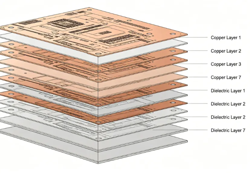
The stackup configuration forms the foundation of any 14-layer automotive PCB. Engineers arrange signal layers, power planes, and ground planes in a symmetric sequence to control warpage and maintain consistent dielectric spacing. High-temperature PCB materials with glass transition temperatures above 170 degrees Celsius help prevent delamination during reflow and underhood operation. Coefficient of thermal expansion values must closely match those of attached components to avoid stress on solder joints during thermal cycling.
Vibration resistant PCB features include strategic placement of mounting holes and the use of additional copper balancing on outer layers. Controlled impedance routing on inner layers requires precise dielectric thickness and trace geometry calculations. Blind and buried vias reduce the number of through-holes that can act as stress concentrators under mechanical load. Signal integrity analysis accounts for the increased number of layer transitions that can introduce discontinuities.
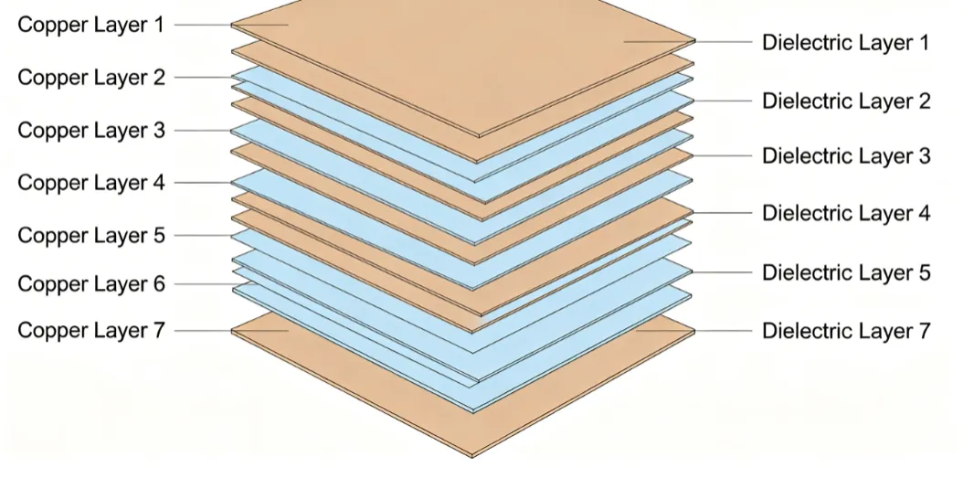
Thermal management principles involve embedding thermal vias or using heavy copper planes to conduct heat away from power devices. Electromagnetic compatibility considerations require dedicated shielding layers or ground planes that surround critical signal traces. These mechanisms work together to satisfy both electrical and mechanical requirements in a single board.
Best Practices for Automotive PCB Design
Designers begin with a detailed requirements review that includes operating temperature range, vibration profiles, and current-carrying needs. Stackup planning occurs early to lock in dielectric materials and copper weights that support both high-speed signals and power delivery. Simulation tools verify impedance targets and thermal performance before layout begins.
Routing guidelines emphasize minimizing layer transitions for critical nets and maintaining adequate spacing from high-voltage areas. Component placement prioritizes mechanical stability by keeping heavy parts near mounting points. Via structures receive careful attention to avoid fatigue under repeated thermal and mechanical stress.
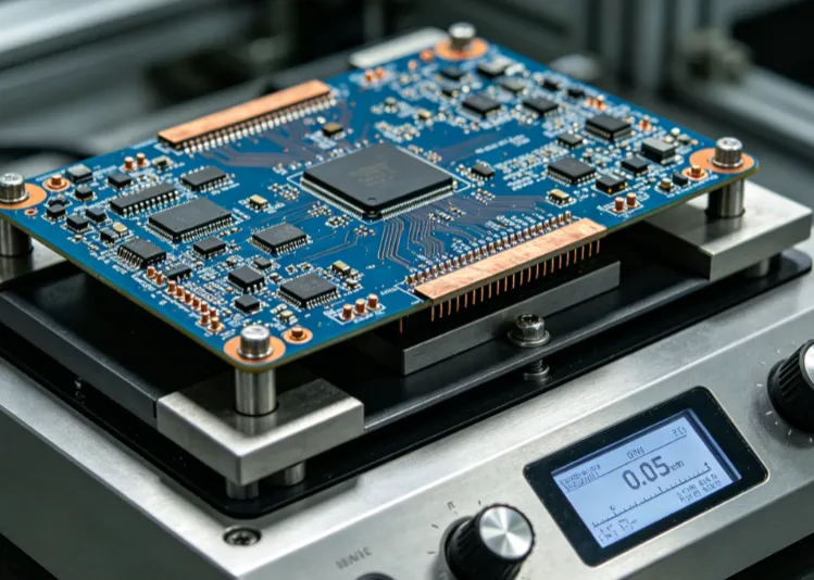
Testing protocols follow established industry standards such as IPC-6012E for qualification and performance of rigid printed boards. Boards undergo thermal cycling, vibration testing, and electrical verification to confirm they meet automotive durability expectations. Documentation of all design decisions supports traceability throughout the product lifecycle.
Practical Considerations for High-Temperature and Vibration Environments
Material selection focuses on laminates rated for continuous operation above 150 degrees Celsius while retaining mechanical strength. Prepreg and core thicknesses are chosen to achieve the required total board thickness without excessive warpage. Copper foil types and surface finishes must withstand the assembly processes and subsequent environmental exposure.
Mechanical reinforcement techniques include the addition of stiffeners or selective copper thieving patterns that balance the board during temperature changes. Edge plating or castellated holes can improve grounding and mechanical attachment in module housings. Designers also evaluate the effects of conformal coating on vibration damping and heat dissipation.
Assembly considerations include solder mask selection that maintains adhesion after thermal aging and component lead finishes compatible with high-temperature soldering profiles. These steps help ensure the finished assembly performs reliably throughout the vehicle service life.
Conclusion
Fourteen-layer PCBs enable the sophisticated electronics required in modern automotive and electric vehicle platforms. Careful attention to stackup symmetry, material properties, and mechanical design features addresses the combined challenges of high temperature and vibration. Following established qualification practices such as those outlined in IPC-A-600K helps confirm that boards meet acceptance criteria before vehicle integration. Engineers who apply these structured considerations achieve designs that balance performance, reliability, and manufacturability.
FAQs
Q1: What design factors are most important for 14-layer PCB automotive applications?
A1: Key factors include symmetric stackup planning, selection of high glass transition temperature materials, controlled impedance routing, and mechanical features that resist vibration. Engineers must also address thermal management through appropriate copper distribution and via placement. These elements together support reliable operation in electric vehicles and other demanding automotive environments.
Q2: How does a 14-layer PCB improve performance in electric vehicles?
A2: The additional layers provide dedicated power and ground planes that reduce noise and improve current handling for inverters and battery management systems. Signal integrity benefits from better isolation between high-speed digital and analog circuits. This construction supports the compact packaging and high reliability needed in modern electric vehicle electronics.
Q3: What standards guide the qualification of automotive PCBs?
A3: Industry standards such as IPC-6012E define qualification and performance requirements for rigid printed boards used in automotive settings. Additional guidance from IPC-A-600K covers visual and dimensional acceptability criteria. Compliance with these standards helps ensure boards withstand the thermal and mechanical stresses typical of vehicle operation.
Q4: How can designers enhance vibration resistance in high-layer-count automotive boards?
A4: Designers enhance vibration resistance through balanced copper distribution, strategic mounting hole placement, and selection of laminates with appropriate mechanical properties. Careful via design and avoidance of stress concentrations further improve durability. These practices align with the mechanical robustness expectations outlined in relevant industry specifications.
References
IPC-6012E — Qualification and Performance Specification for Rigid Printed Boards. IPC, 2017
IPC-A-600K — Acceptability of Printed Boards. IPC, 2020
JEDEC J-STD-020E — Moisture/Reflow Sensitivity Classification. JEDEC, 2014





