 ALLPCB


Are you looking for a cost-effective and sustainable way to create custom breakout boards for your electronics projects? Reusing old PCBs is a fantastic solution for rapid prototyping, especially for hobbyists working on Arduino projects or other DIY endeavors. In this comprehensive guide, we’ll show you how to transform discarded or unused printed circuit boards into functional PCB breakout boards for Arduino prototyping and other applications. Whether you’re aiming for quick PCB prototyping or exploring reusing PCBs for hobby projects, this post will walk you through every step with practical tips and actionable advice.
Why Reuse PCBs for Rapid Prototyping?
Reusing old PCBs offers a range of benefits for hobbyists and engineers alike. Instead of letting unused or broken boards gather dust, you can repurpose them into valuable tools for prototyping. This approach not only saves money but also reduces electronic waste, making it an eco-friendly choice. For rapid prototyping, especially in Arduino prototyping, old PCBs can be turned into custom breakout boards to test circuits, connect components, or simplify complex wiring setups.
Beyond cost savings, repurposing PCBs allows for quick PCB prototyping. You don’t need to wait for new boards to be manufactured or shipped. With a few tools and some creativity, you can adapt what you already have into functional solutions for your projects. Plus, working with existing boards helps you practice essential skills like soldering, circuit tracing, and design optimization.
What Are Breakout Boards and Why Are They Useful?
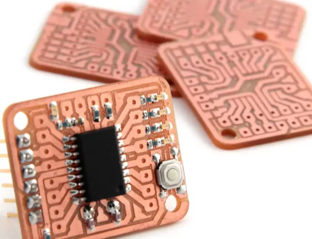
A breakout board is a small PCB designed to make it easier to work with specific components or modules. These boards “break out” the pins or connections of a component into a more accessible format, often with standard spacing for breadboards or headers. For example, a breakout board for a sensor might provide labeled pins and mounting holes, simplifying integration into an Arduino project.
Breakout boards are incredibly useful for Arduino prototyping because they save time and reduce errors. Instead of soldering tiny pins or dealing with messy wiring, you can plug a breakout board into a breadboard or directly connect it to your microcontroller. By reusing PCBs for hobby projects, you can create custom breakout boards tailored to your specific needs without the expense of designing and ordering new ones from scratch.
Benefits of Reusing Old PCBs for Breakout Boards
Let’s dive into the specific advantages of transforming old PCBs into breakout boards for rapid prototyping:
- Cost-Effective: Reusing materials you already have eliminates the need to purchase new boards or components. This is ideal for hobbyists on a budget.
- Time-Saving: For quick PCB prototyping, repurposing an existing board is much faster than waiting for a new design to be fabricated.
- Customizable: Old PCBs can be cut, drilled, or modified to fit the exact specifications of your project, giving you full control over the design.
- Sustainable: Repurposing electronics reduces waste and contributes to a greener approach to prototyping.
- Learning Opportunity: Working with old boards teaches valuable skills like reverse-engineering circuits, soldering, and troubleshooting.
Steps to Turn Old PCBs into Custom Breakout Boards
Now that you understand the benefits, let’s walk through the process of reusing PCBs for hobby projects by turning them into custom breakout boards. Follow these steps to ensure a successful transformation.
Step 1: Gather Materials and Tools
Before you start, collect the necessary tools and materials. Here’s a basic list to get you started:
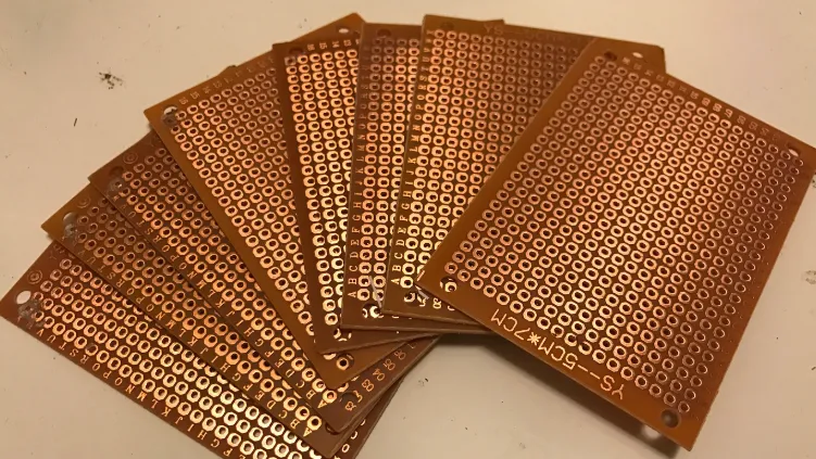
- Old or unused PCBs (from broken devices, failed projects, or surplus stock)
- Cutting tools (hacksaw, rotary tool, or PCB cutter)
- Soldering iron and solder
- Desoldering tools (solder wick or desoldering pump)
- Drill or rotary tool for creating holes
- Multimeter for testing connections
- Header pins or connectors
- Sandpaper or a file for smoothing edges
- Safety gear (gloves, goggles)
Make sure your workspace is well-ventilated and safe for soldering and cutting activities.
Step 2: Assess the Old PCB
Examine the PCB you plan to reuse. Look for usable sections with intact copper traces or pads that can serve as connection points for your breakout board. If the board has components soldered onto it, decide whether to remove them using desoldering tools or work around them. Use a multimeter to test for continuity and ensure there are no short circuits or damaged traces that could interfere with your design.
For Arduino prototyping, identify areas of the board that can accommodate standard 0.1-inch (2.54mm) header spacing, which matches most breadboards and Arduino pin layouts. This will make integration seamless.
Step 3: Plan Your Breakout Board Layout
Sketch a rough design of how you want your PCB breakout board to function. Determine where to place header pins, mounting holes, or additional components. For example, if you’re creating a breakout board for a sensor with 6 pins, plan where each pin will connect on the PCB and how it will interface with your Arduino.
Keep signal integrity in mind. Avoid placing high-speed signal traces near noisy components or power lines to prevent interference. If you’re unsure about impedance, aim for short, direct traces to minimize resistance—typically, a trace resistance of less than 0.1 ohms per inch is ideal for low-power hobby projects.
Step 4: Cut and Shape the PCB
Use a cutting tool to trim the PCB to the desired size and shape. For small breakout boards, a size of 1-2 inches (2.5-5 cm) square is often sufficient. Sand down rough edges to avoid injury and ensure a clean look. If needed, drill holes for mounting or header pins using a small drill bit (e.g., 1mm for standard headers).
Step 5: Remove Unnecessary Components and Traces
If the PCB has unwanted components or traces, carefully desolder them using a desoldering pump or wick. Clean the area with isopropyl alcohol to remove flux residue. For traces that aren’t needed, you can use a hobby knife or rotary tool to cut through the copper, isolating specific sections of the board for your design.
Step 6: Add Headers and Connections
Solder header pins or connectors to the designated spots on the board. Ensure the spacing matches your intended use—standard breadboard spacing (0.1 inches or 2.54mm) is ideal for most Arduino prototyping setups. Test the connections with a multimeter to confirm there are no shorts or open circuits.
Step 7: Test and Integrate into Your Project
Once your breakout board is ready, connect it to your Arduino or breadboard and test its functionality. For example, if you’ve created a breakout for an I2C sensor, verify that the Arduino can communicate with it at the expected speed (typically 100-400 kHz for I2C). Debug any issues by checking solder joints and trace continuity.
Tips for Successful PCB Reuse in Hobby Projects
To make the most of reusing PCBs for hobby projects, keep these practical tips in mind:
- Start Small: If you’re new to PCB reuse, begin with simple breakout boards for basic components like LEDs or resistors before tackling complex modules.
- Document Your Work: Label connections on your breakout board or keep a diagram of the layout. This helps with troubleshooting and future modifications.
- Prioritize Safety: Always wear protective gear when cutting or soldering, and work in a well-ventilated area to avoid inhaling fumes.
- Use Quality Tools: Invest in a decent soldering iron (25-40W range for hobbyists) and a reliable multimeter to ensure accurate work.
- Experiment with Designs: Don’t be afraid to iterate. If a breakout board doesn’t work as expected, analyze the issue and try a different approach.
Common Challenges and How to Overcome Them
While quick PCB prototyping through reuse is rewarding, it can come with challenges. Here are some common issues and solutions:
- Damaged Traces: If copper traces are broken, use small jumper wires or conductive paint to bridge the gaps. Test with a multimeter to ensure continuity.
- Component Removal Issues: Stubborn components can be tricky to desolder. Apply heat evenly and use a desoldering pump to avoid damaging the board.
- Size Constraints: If the PCB is too large, carefully plan cuts to retain usable areas. Use a ruler or template for precision.
- Signal Noise: For high-speed signals (e.g., SPI at 1-10 MHz), keep traces short and avoid crossing power lines. Add decoupling capacitors (e.g., 0.1μF) near ICs to reduce noise.
Creative Ideas for Custom Breakout Boards
Reusing old PCBs opens up endless possibilities for PCB breakout boards. Here are a few ideas to inspire your next project:
- Sensor Breakouts: Create boards for temperature, humidity, or motion sensors with labeled pins for easy Arduino integration.
- Power Distribution Boards: Design a small board to split a single power source (e.g., 5V from Arduino) into multiple outputs for LEDs or motors.
- Communication Modules: Build breakouts for I2C or SPI devices, ensuring clean signal paths for reliable data transfer.
- Custom Shields: Adapt an old PCB into a compact shield for your Arduino, stacking directly onto the board for a tidy setup.
Conclusion: Start Reusing PCBs Today
Reusing old PCBs for rapid prototyping is a smart, sustainable, and budget-friendly way to create custom PCB breakout boards. Whether you’re diving into Arduino prototyping or experimenting with other electronics, this approach offers endless opportunities to innovate while reducing waste. By following the steps outlined in this guide, you can master quick PCB prototyping and transform discarded boards into valuable tools for your hobby projects.
With just a few tools and some creativity, you can breathe new life into old electronics and take your projects to the next level. So, dig through your scrap bin, grab an old PCB, and start prototyping today!


