 ALLPCB


If you're dealing with a malfunctioning MRI machine and suspect issues with its printed circuit boards (PCBs), you're in the right place. This guide offers a practical, step-by-step approach to MRI PCB repair, covering PCB troubleshooting, fault isolation, component replacement, and rework techniques. Whether you're a biomedical engineer or a technician, you'll find actionable advice to help diagnose and fix PCB issues efficiently. Let's dive into the detailed process to ensure your MRI equipment runs smoothly again.
Why MRI Machine PCBs Are Critical and Prone to Issues
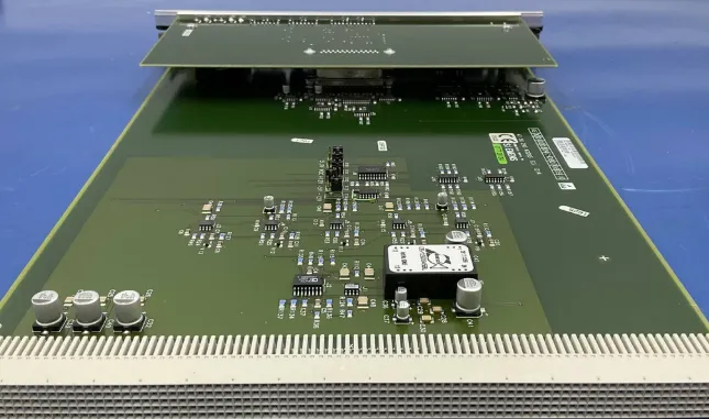
MRI machines are complex medical devices that rely heavily on PCBs to control critical functions like signal processing, power management, and data acquisition. These boards handle high-frequency signals, often in the range of 64 MHz to 128 MHz for common 1.5T and 3T MRI systems, and must operate with precision to ensure accurate imaging. However, due to constant operation, exposure to electromagnetic interference (EMI), and high power loads, PCBs in MRI machines are susceptible to failures such as component burnout, trace damage, or signal degradation.
Understanding the importance of these boards and their common issues is the first step in effective troubleshooting. Failures can lead to distorted images, system downtime, or complete machine failure, impacting patient care and operational costs. By mastering MRI PCB repair, you can minimize these risks and extend the lifespan of your equipment.
Step 1: Initial Diagnosis and Safety Precautions
Before diving into PCB troubleshooting, ensure safety first. MRI machines operate with high voltages and strong magnetic fields, so always power down the system and follow manufacturer safety guidelines. Use proper personal protective equipment (PPE) and ensure the workspace is free from magnetic hazards.
Start with a preliminary diagnosis by gathering information about the issue. Check error codes or logs from the MRI system’s software. For instance, an error indicating "RF signal loss" might point to a problem in the radio frequency (RF) amplifier circuit on the PCB. Document symptoms like system crashes, image artifacts, or failure to initialize, as these clues will guide your fault isolation process.
Step 2: Visual Inspection for Obvious Damage
Begin PCB troubleshooting with a thorough visual inspection. Use a magnifying glass or a digital microscope to examine the board for signs of damage. Look for:
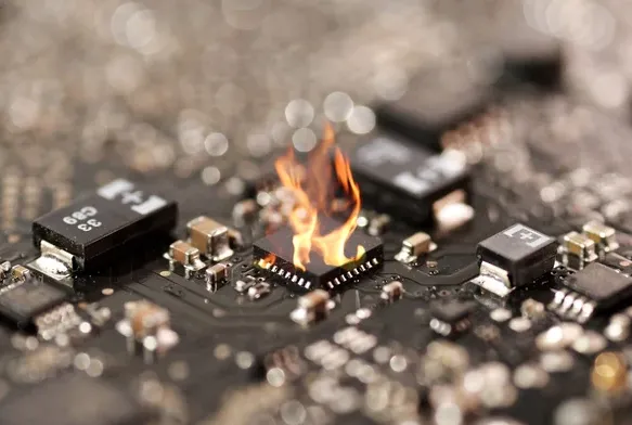
- Burn marks or discoloration, which could indicate overheating components.
- Swollen or leaking capacitors, often a sign of failure due to high voltage stress.
- Cracked or broken traces, which disrupt signal flow and are common in high-vibration environments.
- Loose or damaged connectors, which can cause intermittent signal issues.
If you spot any of these issues, note their location on the board. For example, a burned resistor near the power input might suggest an overcurrent problem, pointing to a specific circuit area for further testing.
Step 3: Fault Isolation Using Diagnostic Tools
Once you've identified potential problem areas, move to fault isolation. This step involves narrowing down the exact source of the issue using diagnostic tools. Here are the key tools and methods to use:
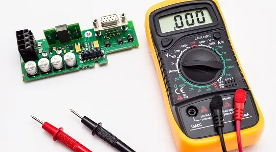
Multimeter for Continuity and Voltage Testing
A digital multimeter is essential for checking continuity in traces and measuring voltage across components. For instance, if you're testing a power supply circuit on the PCB, ensure the input voltage matches the expected value, such as 12V or 24V, as per the schematic. A reading of 0V or significantly lower could indicate a failed voltage regulator or a short circuit.
Oscilloscope for Signal Analysis
An oscilloscope helps analyze signal integrity, especially in RF circuits critical to MRI machines. If the system reports image distortion, check the RF signal output on the PCB. A typical 1.5T MRI system should show a clean sine wave at around 64 MHz. Noise or irregular waveforms could point to a faulty amplifier or capacitor in the signal path.
Thermal Imaging Camera
Use a thermal imaging camera to detect hot spots on the PCB. Excessive heat, often above 80°C for standard components, can indicate failing parts like power transistors or resistors under stress. This method is particularly useful for identifying issues that aren't visible to the naked eye.
By combining these tools, you can pinpoint the faulty section of the PCB, whether it's a power circuit, signal processing area, or control module. Document your findings to create a clear repair plan.
Step 4: Component Replacement for Damaged Parts
After isolating the fault, the next step in MRI PCB repair is component replacement. Replacing components requires precision and the right tools to avoid further damage to the board. Follow these steps:
Identify the Faulty Component
Using your diagnostic results, identify the specific component to replace. For example, if a capacitor in the power circuit shows a voltage drop or physical swelling, it’s likely the culprit. Cross-check the component’s part number with the PCB schematic or bill of materials (BOM) to ensure you source an exact match.
Desoldering the Old Component
Use a soldering station with a fine tip and a desoldering pump or wick to remove the faulty component. Set the temperature to around 300°C for most PCB components to avoid damaging nearby traces. For surface-mount devices (SMDs), which are common in MRI PCBs, use hot air rework stations to heat the component evenly and lift it off without stress.
Soldering the New Component
Align the replacement component correctly, ensuring polarity is observed for capacitors and diodes. Apply flux to the pads, then solder the component in place with minimal heat exposure. For a typical SMD capacitor, soldering should take no more than 2-3 seconds per pad to prevent thermal damage.
After replacement, clean the area with isopropyl alcohol and a brush to remove flux residue, which can cause corrosion over time. Test the circuit again with a multimeter to confirm proper operation.
Step 5: Rework Techniques for Trace and Pad Repair
In some cases, the issue may not be with a component but with the PCB itself, such as damaged traces or pads. Mastering rework techniques is crucial for restoring functionality. Here’s how to approach this:
Repairing Broken Traces
If a trace is cracked or broken, use a conductive epoxy or a small jumper wire to bridge the gap. Scrape away the solder mask over the trace with a fine blade to expose the copper, then apply the conductive material. Ensure the repair can handle the current load; for high-power MRI circuits, a jumper wire rated for at least 2A is often safer.
Restoring Damaged Pads
For lifted or damaged solder pads, use a pad repair kit. These kits include adhesive copper foil that you can cut to size and bond to the PCB. After securing the new pad, solder the component back in place. This technique is especially useful for RF connectors on MRI PCBs, which often experience mechanical stress.
Always test the repaired area for continuity and signal integrity. A poorly repaired trace can introduce noise or impedance mismatches, especially in high-frequency circuits operating at 128 MHz for 3T MRI systems.
Step 6: Post-Repair Testing and Validation
Once repairs are complete, thorough testing is essential to ensure the MRI machine functions correctly. Reinstall the PCB into the system and power it on in a controlled environment. Monitor for error codes and run a diagnostic scan to check signal quality. For example, verify that the RF output amplitude and frequency match the expected values (e.g., 64 MHz with minimal noise for a 1.5T system).
Additionally, perform a test scan using a phantom (a standardized test object) to confirm image quality. Look for artifacts or distortions that could indicate lingering PCB issues. If everything checks out, document the repair process for future reference, noting the tools used, components replaced, and test results.
Preventive Maintenance to Avoid Future PCB Failures
Preventing PCB issues is just as important as repairing them. Implement regular maintenance routines to extend the life of MRI machine PCBs. Here are some tips:
- Clean Regularly: Dust and debris can cause shorts or overheating. Use compressed air or specialized electronics cleaners to keep PCBs clean.
- Monitor Temperatures: Ensure cooling systems are functioning, as excessive heat (above 70°C for prolonged periods) can degrade components.
- Check for EMI: Use shielding or grounding techniques to minimize electromagnetic interference, which can disrupt high-frequency signals.
- Schedule Inspections: Perform visual and electrical inspections every 6 months to catch early signs of wear or failure.
By staying proactive, you can reduce the frequency of repairs and keep your MRI system operational with minimal downtime.
Challenges in MRI PCB Repair and How to Overcome Them
Repairing MRI PCBs comes with unique challenges due to the complexity and sensitivity of the equipment. Here are common obstacles and solutions:
Access to Schematics and Parts
MRI machine schematics and replacement parts can be hard to obtain due to proprietary designs. Work with authorized service providers or consult technical forums for alternative sourcing options. When possible, stock common components like capacitors and resistors in various ratings (e.g., 10uF, 100V) to avoid delays.
High-Frequency Circuit Sensitivity
High-frequency circuits are prone to noise and impedance issues after repair. Use precision tools and test equipment to ensure repairs don’t alter circuit characteristics. For instance, after replacing an RF component, measure the circuit’s impedance (typically around 50 ohms for RF lines) to confirm compatibility.
Limited Workspace
MRI machines often have cramped internal spaces, making PCB access difficult. Use extension tools or modular repair kits to work efficiently in tight areas. Plan the repair process to minimize disassembly time.
Conclusion: Mastering MRI PCB Repair for Reliable Performance
Troubleshooting and repairing MRI machine PCBs is a meticulous but rewarding process. By following a structured approach to PCB troubleshooting, fault isolation, component replacement, and rework techniques, you can restore functionality to critical medical equipment. Start with a detailed diagnosis, use the right tools for testing and repair, and prioritize preventive maintenance to avoid future issues. With the insights and steps provided in this guide, you're well-equipped to tackle MRI PCB repair challenges and ensure consistent, high-quality performance from your MRI systems.
Remember, patience and precision are key. Each repair builds your expertise, helping you handle even the most complex PCB issues with confidence. Keep learning, stay updated on best practices, and maintain a well-organized toolkit to make every repair a success.


