 ALLPCB


Designing high-speed digital circuits, such as those for DDR5 memory, gigabit Ethernet, or other advanced applications, requires precision and the right tools. If you're searching for the best PCB design software for high-speed digital circuits, you're in the right place. This guide will help you navigate the critical features to look for, including support for impedance control, signal integrity analysis, and high-speed routing. We'll dive deep into each aspect to ensure you can make an informed decision for your next project, whether it involves DDR5 designs or gigabit Ethernet layouts.
Why High-Speed Digital Circuits Demand Specialized PCB Design Software
High-speed digital circuits operate at frequencies where signal integrity becomes a major concern. At speeds above 1 GHz, such as those seen in DDR5 memory (up to 8.4 GT/s) or gigabit Ethernet (1 Gbps and beyond), even small design flaws can lead to signal degradation, crosstalk, or electromagnetic interference (EMI). Standard PCB design tools often lack the advanced features needed to handle these challenges. Specialized software offers tools for impedance control, signal integrity analysis, and optimized routing to ensure reliable performance.
In this guide, we'll explore the key features you need in PCB design software for high-speed applications and provide actionable tips to help you choose the right tool for your needs.
Key Features to Look for in PCB Design Software for High-Speed Digital Circuits
When selecting software for high-speed digital circuits, certain features are non-negotiable. Below, we break down the essential capabilities to prioritize, targeting specific needs like DDR5 designs, impedance control, and gigabit Ethernet layouts.
1. Advanced Impedance Control Tools for Precision Design
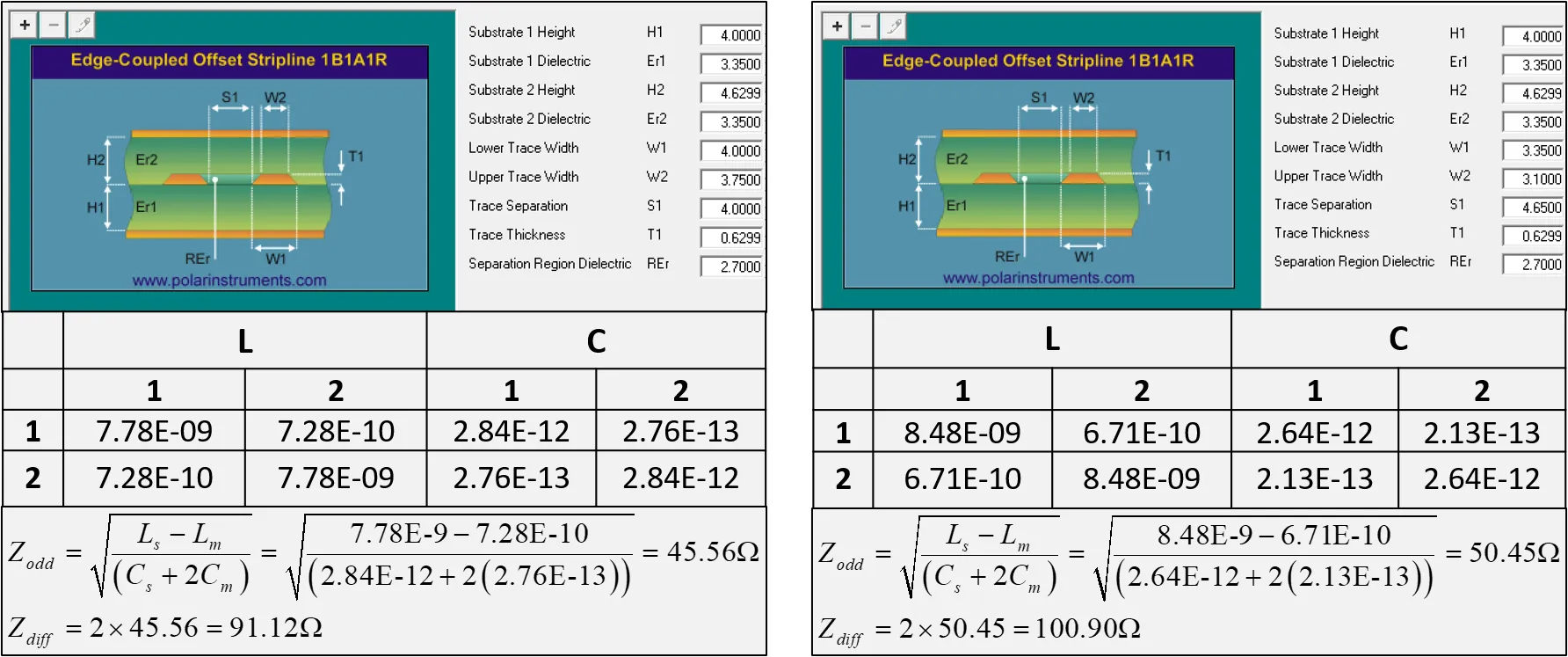
Impedance control is critical in high-speed designs to ensure signals travel without reflection or loss. For DDR5, which requires tight impedance tolerances (often around 40-60 ohms for single-ended signals), the software must calculate and maintain consistent trace impedance across the board. Look for tools that allow you to define stack-up configurations, specify trace widths, and simulate impedance based on material properties like dielectric constant (Dk) and loss tangent (Df).
Effective impedance control software will also support differential pair routing, commonly used in gigabit Ethernet designs, where pairs must maintain a specific impedance (typically 100 ohms). The ability to simulate and adjust for manufacturing variations ensures your design remains robust even after fabrication.
2. Signal Integrity Analysis Tools for Reliable Performance
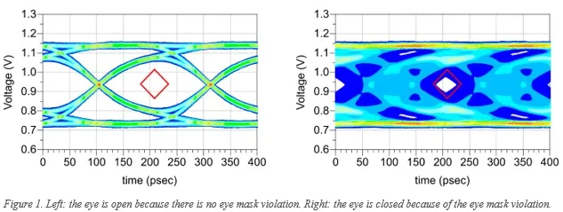
Signal integrity (SI) issues, such as crosstalk, overshoot, and ringing, can ruin high-speed designs. Software with built-in signal integrity analysis tools can simulate how signals behave under real-world conditions. For DDR5 circuits, where data rates exceed 6 GT/s, SI tools help identify and mitigate issues like inter-symbol interference (ISI) by analyzing eye diagrams and jitter.
For gigabit Ethernet designs, SI tools are vital for ensuring clean signal transmission over long traces. Look for software that offers pre-layout and post-layout simulations, allowing you to test signal paths before and after routing. Features like S-parameter analysis and time-domain reflectometry (TDR) can pinpoint impedance mismatches or discontinuities in your design.
3. High-Speed Routing Software for Optimized Layouts
Routing high-speed signals requires precision to minimize delays and interference. High-speed routing software should offer features like length matching, differential pair routing, and automated trace tuning. In DDR5 designs, for instance, signal traces must be length-matched within tight tolerances (often less than 5 mils) to prevent timing skews. Software that automates this process saves time and reduces errors.
For gigabit Ethernet, routing software must handle complex layouts with minimal vias and short signal paths to reduce latency and EMI. Look for tools that support interactive routing with real-time feedback on signal delays and impedance, ensuring your layout meets high-speed requirements.
4. Support for Multi-Layer Designs and Stack-Up Planning
High-speed circuits often require multi-layer boards to separate power, ground, and signal planes, reducing noise and improving signal quality. Software for high-speed PCB design should allow detailed stack-up planning, letting you define layer thickness, material properties, and via structures. For DDR5 and gigabit Ethernet, a typical stack-up might include 8-12 layers, with dedicated ground planes adjacent to signal layers to minimize loop inductance.
The ability to simulate the impact of stack-up on impedance and signal integrity is a bonus, as it helps you optimize the design before fabrication.
5. Integration with Simulation and Testing Tools
Beyond design and routing, the best software integrates with simulation tools for thermal, power integrity (PI), and EMI analysis. High-speed circuits generate significant heat and power demands, especially in DDR5 applications with high data rates. Software that simulates decoupling capacitor placement and power distribution network (PDN) performance ensures stable operation.
For gigabit Ethernet designs, EMI simulation helps identify potential interference sources, allowing you to adjust layouts or add shielding as needed. Seamless integration with third-party simulation tools or built-in modules can streamline your workflow.
How to Choose the Right PCB Design Software for Your Project
With the key features in mind, selecting the right software for high-speed digital circuits involves evaluating your specific needs and constraints. Here’s a step-by-step approach to guide your decision.
Step 1: Define Your Project Requirements
Start by outlining the specifics of your design. Are you working on a DDR5 memory module requiring data rates above 6 GT/s? Or a gigabit Ethernet board with strict latency requirements? List the critical parameters, such as frequency, impedance targets (e.g., 50 ohms for single-ended DDR5 signals), and layer count. This clarity helps narrow down software options that meet your technical needs.
Step 2: Evaluate Software Capabilities
Compare the features of different tools based on the criteria discussed earlier. Prioritize software with robust impedance control and signal integrity analysis for DDR5 or gigabit Ethernet projects. Check if the software supports automation for high-speed routing to save time on complex layouts. Many tools offer free trials or demos, so take advantage of these to test their capabilities on a small portion of your design.
Step 3: Consider Ease of Use and Learning Curve
High-speed design software can be complex, especially for engineers new to advanced PCB layouts. Look for tools with intuitive interfaces, detailed documentation, and active user communities for support. A steep learning curve might delay your project, so balance advanced features with usability.
Step 4: Assess Cost and Scalability
Budget is a practical concern for many engineers and companies. Some software offers tiered pricing based on features, with basic versions for smaller projects and premium editions for complex high-speed designs. Consider whether the software can scale with your future needs, supporting larger boards or higher frequencies as technology evolves (e.g., moving from DDR5 to future standards).
Practical Tips for Designing High-Speed Digital Circuits
Beyond choosing the right software, successful high-speed PCB design requires attention to best practices. Here are actionable tips tailored to DDR5, gigabit Ethernet, and other high-speed applications.
Tip 1: Prioritize Ground Planes and Power Integrity
A solid ground plane is essential for reducing noise in high-speed designs. Place ground planes directly below signal layers to provide a low-impedance return path. For DDR5, ensure decoupling capacitors (e.g., 0.1 μF ceramics) are placed close to memory chips to stabilize power delivery. Simulate the PDN to avoid voltage drops during high-frequency switching.
Tip 2: Minimize Via Usage in Signal Paths
Vias introduce inductance and impedance discontinuities, degrading signal quality in high-speed circuits. For gigabit Ethernet traces, route signals on a single layer whenever possible. If vias are unavoidable, use back-drilling or micro-vias to reduce stub effects, and simulate their impact using signal integrity tools.
Tip 3: Match Trace Lengths for Timing Accuracy
In DDR5 designs, mismatched trace lengths cause timing skews, leading to data errors. Use high-speed routing software to match lengths within tight tolerances (e.g., ±5 mils for DDR5 clock signals). Serpentine routing can add length to shorter traces, but keep bends smooth to avoid signal reflections.
Tip 4: Test and Iterate with Simulations
Simulations are your best friend in high-speed design. Use signal integrity analysis tools to test for crosstalk and reflections before fabrication. For gigabit Ethernet, simulate worst-case scenarios, like maximum cable length, to ensure reliability. Iterate on your design based on simulation results to catch issues early.
Common Challenges in High-Speed PCB Design and How Software Helps
High-speed digital circuits present unique challenges that can derail a project if not addressed. Here’s how the right PCB design software can help overcome these hurdles.
Challenge 1: Managing Signal Reflections
At high frequencies, mismatched impedance causes signal reflections, degrading performance. Impedance control software calculates trace dimensions and stack-up configurations to maintain consistent impedance (e.g., 100 ohms for gigabit Ethernet differential pairs), minimizing reflections.
Challenge 2: Reducing Crosstalk
Closely spaced traces in DDR5 layouts can couple, causing crosstalk. Software with signal integrity analysis tools simulates crosstalk effects and suggests spacing or shielding solutions, such as guard traces or ground vias, to isolate sensitive signals.
Challenge 3: Meeting Tight Timing Requirements
High-speed designs like DDR5 demand precise timing. Routing software automates length matching and delay tuning, ensuring signals arrive at their destination within specified windows (e.g., less than 50 ps skew for DDR5 data lines).
Why Partner with a Trusted PCB Manufacturer?
Even with the best PCB design software for high-speed digital circuits, the final product depends on manufacturing quality. Partnering with a reliable PCB manufacturer ensures your design translates accurately to the physical board. Look for a provider with expertise in high-speed designs, offering tight control over impedance (within ±5% tolerance) and advanced stack-up capabilities for multi-layer boards. A manufacturer that supports design review and feedback can catch potential issues before production, saving time and cost.
At ALLPCB, we specialize in bringing high-speed designs to life, whether for DDR5 memory modules or gigabit Ethernet applications. Our advanced fabrication processes and quality assurance ensure your boards meet the strictest performance standards.
Conclusion: Finding the Perfect PCB Design Software for High-Speed Digital Circuits
Choosing the best PCB design software for high-speed digital circuits comes down to identifying tools that support your specific needs, from impedance control for DDR5 to signal integrity analysis for gigabit Ethernet. Focus on software with advanced features like high-speed routing, simulation capabilities, and stack-up planning to ensure reliable performance at frequencies above 1 GHz. By following the steps and tips in this guide, you can select a tool that streamlines your workflow and helps deliver cutting-edge designs.
Remember, the right software is only part of the equation. Partnering with a trusted manufacturer like ALLPCB ensures your high-speed designs are fabricated with precision, meeting the demands of modern digital applications. Start exploring your software options today and take your PCB designs to the next level.


