 ALLPCB


Are you struggling with electromagnetic interference (EMI) in your engine control unit (ECU) PCB designs? For automotive applications, minimizing EMI is critical to ensure reliability, meet EMC compliance standards, and prevent noise from disrupting critical systems. In this comprehensive guide, we'll explore proven ECU PCB EMI reduction techniques, strategies for automotive PCB EMC compliance, methods for engine control unit noise filtering, and the benefits of shielded PCB design for ECUs. Whether you're an electrical engineer or a PCB designer working in the automotive industry, this post will provide actionable insights to enhance your designs.
Why EMI Matters in ECU PCB Design
Electromagnetic interference (EMI) is a major concern in automotive electronics, especially for ECUs, which are the brain of a vehicle’s engine management system. ECUs control critical functions like fuel injection, ignition timing, and emission controls. Any interference can lead to malfunctions, reduced performance, or even safety hazards. With the rise of electric vehicles (EVs) and advanced driver-assistance systems (ADAS), the electronic content in vehicles has surged, increasing the risk of EMI.
EMI can originate from internal sources (like switching regulators or high-speed digital signals) or external sources (like radio frequency interference from nearby devices). To ensure reliability, automotive ECUs must comply with strict electromagnetic compatibility (EMC) standards, such as ISO 11452 for immunity and CISPR 25 for emissions. Failing to address EMI can result in costly redesigns, failed compliance tests, or, worse, field failures.
Understanding EMI and EMC in Automotive PCBs
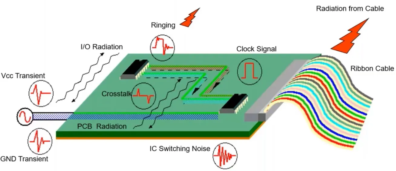
Before diving into solutions, let's clarify the terms. EMI refers to unwanted electromagnetic energy that can disrupt electronic circuits. EMC, or electromagnetic compatibility, is the ability of a device to operate in its environment without causing or being affected by EMI. For automotive PCBs, achieving EMC means designing ECUs that neither emit excessive interference nor are overly sensitive to external noise.
In the automotive world, ECUs are exposed to harsh conditions—temperature swings from -40°C to 85°C, vibrations, and a noisy electromagnetic environment. A poorly designed PCB can act like an antenna, radiating or picking up interference. For example, a high-speed signal trace running parallel to a power line can couple noise, leading to signal integrity issues. This is why automotive PCB EMC compliance is non-negotiable.
Key ECU PCB EMI Reduction Techniques
Let's explore practical strategies to minimize EMI in ECU PCB designs. These techniques are tailored for electrical engineers looking to improve reliability and pass stringent EMC tests.
1. Optimize PCB Layout for EMI Control
The layout of your PCB is the first line of defense against EMI. A well-thought-out design can prevent noise coupling and radiation. Here are key layout tips:
- Separate Analog and Digital Sections: Keep analog and digital circuits apart to avoid crosstalk. For instance, place sensitive analog sensors away from noisy digital microcontroller signals.
- Minimize Loop Areas: High-current loops, especially in power supply lines, can radiate EMI. Keep return paths short and direct. For example, place decoupling capacitors close to IC power pins to reduce loop inductance.
- Use Ground Planes: A solid ground plane acts as a low-impedance return path for signals, reducing noise. Avoid splitting ground planes unless absolutely necessary, as splits can create high-impedance paths that radiate EMI.
- Route High-Speed Signals Carefully: High-speed traces (e.g., clock signals above 10 MHz) should be short, direct, and routed over a continuous ground plane to minimize radiation.
Recommended Reading: Switch PCB Layout: Best Practices for Reducing EMI and Noise
2. Implement Proper Grounding Techniques
Grounding is critical for ECU PCB EMI reduction techniques. A poor grounding strategy can turn your PCB into an EMI radiator. Follow these practices:
- Star Grounding for Sensitive Circuits: Use a single-point grounding (star grounding) for analog circuits to prevent ground loops. Connect all grounds to a single point near the power supply return.
- Multi-Layer Ground Planes: In multi-layer PCBs, dedicate entire layers to ground planes. This provides a low-impedance path and shields internal signal layers from external interference.
- Avoid Ground Loops: Ground loops occur when multiple ground paths create a loop, acting as an antenna for EMI. Ensure all ground connections follow a hierarchical structure back to the main ground point.
For example, in a 4-layer ECU PCB, layers 2 and 3 can be dedicated to ground and power planes, respectively, with signal traces on layers 1 and 4. This configuration reduces noise coupling and improves signal integrity.
3. Use Decoupling and Filtering for Engine Control Unit Noise Filtering
Power supply noise is a common source of EMI in ECUs. Switching regulators and digital circuits generate high-frequency noise that can propagate through the system. Effective engine control unit noise filtering requires strategic use of decoupling capacitors and filters:
- Decoupling Capacitors: Place low-ESR ceramic capacitors (e.g., 0.1 μF and 1 μF) close to each IC's power pins. These capacitors filter out high-frequency noise, preventing it from affecting sensitive circuits.
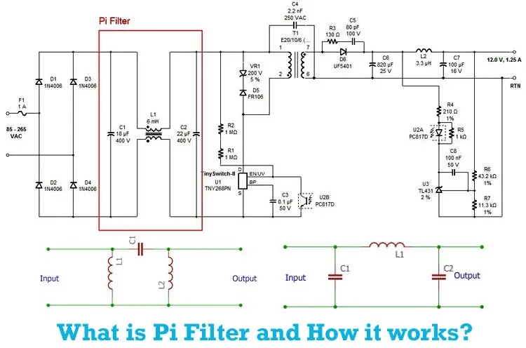
- PI Filters: Use PI filters (capacitor-inductor-capacitor) on power lines to suppress noise. For instance, a PI filter with a 10 μH inductor and 10 μF capacitors can attenuate noise above 100 kHz.
- Ferrite Beads: Add ferrite beads in series with power lines to block high-frequency noise while allowing DC current to pass. Choose beads with a current rating matching your circuit (e.g., 1A for low-power ECUs).
Testing with an oscilloscope can reveal noise levels on power rails. If you observe ripple voltages exceeding 50 mV peak-to-peak, consider adding more decoupling or upgrading your filter design.
4. Incorporate Shielded PCB Design for ECUs
Shielding is a powerful method to block external EMI and contain internal emissions. Shielded PCB design for ECUs can significantly improve reliability in noisy automotive environments. Consider these approaches:
- Metal Enclosures: House the ECU in a conductive metal enclosure to create a Faraday cage, blocking external EMI. Ensure the enclosure is properly grounded to the PCB ground plane.
- Shielding Layers: In multi-layer PCBs, use inner layers as shielding planes connected to ground. This isolates sensitive traces from external interference.
- Component-Level Shielding: Use metal shields over high-radiation components like oscillators or RF modules. For example, a 1 mm thick aluminum shield can reduce radiated EMI by up to 20 dB at 100 MHz.
Shielding effectiveness depends on material and design. Conductive gaskets and proper grounding of the shield are essential to avoid gaps that allow EMI leakage.
5. Select Low-EMI Components
Component choice plays a big role in EMI performance. Opt for components designed for low EMI:
- Low-Noise Regulators: Use linear regulators or low-EMI switching regulators with integrated filters. For instance, Texas Instruments'TPS7A series offers low-noise LDOs ideal for automotive applications.
- Spread-Spectrum Clocks: Use spread-spectrum clock generators to reduce peak EMI emissions by spreading energy over a wider frequency range.
- Filtered Connectors: Choose connectors with built-in EMI filters for external interfaces to prevent noise from entering or leaving the ECU.
Ensuring Automotive PCB EMC Compliance
Meeting automotive PCB EMC compliance standards is not just about passing tests—it's about ensuring real-world reliability. Automotive EMC standards like CISPR 25 (for radiated and conducted emissions) and ISO 11452 (for immunity) set strict limits. For example, CISPR 25 Class 5 limits conducted emissions to 30 dBμV in the 150 kHz to 30 MHz range for critical automotive systems.
To ensure compliance:
- Pre-Compliance Testing: Use EMI test equipment during development to identify issues early. Conducted emission tests can reveal noise on power lines, while radiated emission tests detect PCB radiation.
- Simulate EMI Performance: Use simulation tools like ANSYS HFSS or Altium Designer to model EMI behavior. Simulations can predict noise coupling and help optimize layouts before fabrication.
- Follow Design Standards: Adhere to automotive design guidelines, such as those from the Automotive Electronics Council (AEC-Q100 for component qualification), to ensure robustness.
Real-World Challenges and Solutions
Designing ECUs for automotive reliability isn’t just theoretical—it’s a battle against real-world challenges. I recall a project where an ECU failed EMC testing due to radiated emissions from a high-speed CAN bus interface. The issue was traced to long, unshielded traces acting as antennas. By rerouting the traces over a ground plane and adding a common-mode choke, emissions dropped by 15 dB, passing the test.
Another challenge is balancing cost and performance. High-end shielding and low-EMI components can increase BOM costs by 20-30%. However, investing in EMI mitigation upfront saves money compared to redesigns or field failures. Start with simulation and pre-compliance testing to catch issues early.
Conclusion: Building Reliable ECU PCBs with Minimal EMI
Minimizing EMI in ECU PCB design is essential for automotive reliability and automotive PCB EMC compliance. By optimizing layouts, using solid grounding, applying engine control unit noise filtering, and incorporating shielded PCB design for ECUs, you can significantly reduce interference. These ECU PCB EMI reduction techniques not only help pass EMC tests but also ensure your designs perform reliably in the harsh automotive environment.
As an electrical engineer, focus on iterative design and testing. Use simulation tools, select low-EMI components, and prioritize grounding and shielding. The result? ECUs that power vehicles safely and efficiently, even under the toughest conditions.


