 ALLPCB


If you're looking for a reliable way to apply solder paste to flexible printed circuit boards (PCBs), a PCB stencil for flex PCBs is the solution you need. These specialized stencils are designed to accommodate the unique properties of flexible circuitry, ensuring precise solder paste application despite the bending and unique shapes of flex circuits. In this comprehensive guide, we'll dive into the world of stencils for flex PCBs, explore how to handle flex circuits effectively, and provide actionable tips for achieving optimal results in your projects.
What Are Flex PCBs and Why Do They Need Special Stencils?
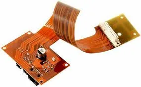
Flexible PCBs, or flex circuits, are a type of printed circuit board made from materials that allow them to bend and conform to various shapes. Unlike rigid PCBs, which are built on solid substrates like FR4, flex PCBs use materials such as polyimide or polyester, enabling them to fit into tight spaces or move dynamically in applications like wearable devices, medical equipment, and automotive systems.
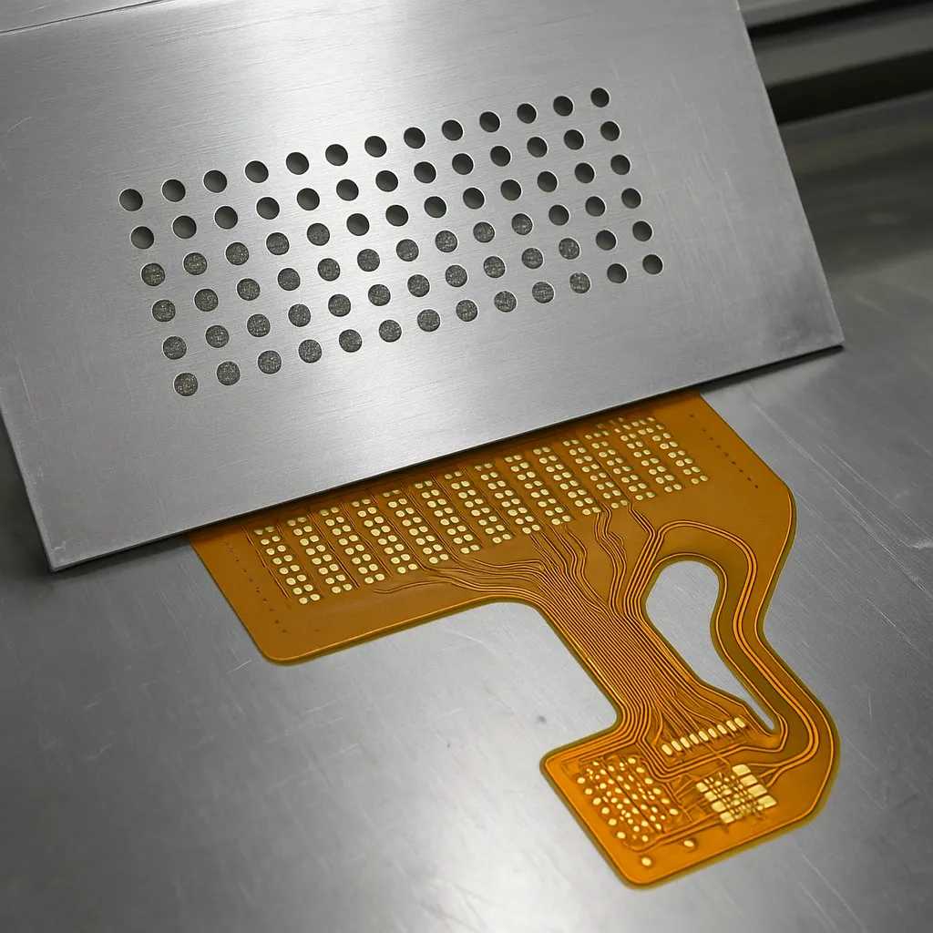
Because of their flexibility, applying solder paste to flex PCBs can be challenging. A standard stencil designed for rigid boards may not align properly or maintain consistent contact with a flexible surface. This is where a specialized stencil for flex PCBs comes into play. These stencils are crafted to adapt to the unique contours and movements of flexible circuitry, ensuring accurate paste deposition for soldering components.
Key Features of a Stencil for Flex PCBs
When choosing or designing a stencil for flex PCBs, several key features must be considered to ensure it meets the needs of handling flex circuits. Here are the critical aspects to look for:
- Material Compatibility: Stencils for flex PCBs are often made from materials like stainless steel or laser-cut polyimide films that can conform to slight bends without deforming. This ensures durability and precision even after multiple uses.
- Thickness: The stencil thickness typically ranges from 0.1mm to 0.15mm for flex circuits, thinner than standard stencils (0.2mm or more) used for rigid boards. This thinner design helps maintain contact with uneven surfaces.
- Aperture Design: Apertures (the openings in the stencil for solder paste) must be precisely engineered to match the smaller pad sizes often found on flex PCBs, preventing excess paste or misalignment.
- Flexibility Support: Some stencils are mounted on specialized frames or use tensioning systems to maintain alignment while allowing the stencil to adapt to the flex PCB's shape during the printing process.
By focusing on these features, a PCB flexible stencil can significantly improve the accuracy of solder paste application, reducing defects like bridging or insufficient paste on fine-pitch components.
Challenges in Handling Flex Circuits During Stencil Printing
Handling flex circuits during stencil printing presents unique challenges compared to rigid PCBs. Understanding these hurdles is essential for achieving high-quality results. Below are some common issues and how a flexible stencil PCB can help address them:
1. Surface Unevenness
Flex PCBs often have uneven surfaces due to their ability to bend or conform to specific shapes during assembly. This can cause gaps between the stencil and the board, leading to uneven solder paste deposition. A well-designed stencil for flex PCBs can minimize this by using materials or tension systems that adapt to surface variations.
2. Alignment Difficulties
Aligning a stencil with a flex PCB can be tricky, especially if the board is not perfectly flat during the printing process. Specialized fixtures or jigs are often used alongside the stencil to hold the flex circuit in place, ensuring precise alignment with the stencil apertures.
3. Risk of Damage
Flexible circuitry is more delicate than rigid boards and can tear or stretch if mishandled during stencil printing. Using a PCB flexible stencil with a soft contact surface or reduced pressure during printing can prevent damage to the board.
Best Practices for Using a Stencil for Flex PCBs
To maximize the effectiveness of your flexible stencil PCB and ensure smooth handling of flex circuits, follow these best practices:
1. Use Proper Support Fixtures
Invest in custom fixtures or jigs that hold the flex PCB flat and secure during the stencil printing process. These supports prevent movement and ensure the stencil maintains consistent contact with the board. For instance, vacuum tables or magnetic holders can be used to stabilize the flex circuit without applying excessive force.
2. Optimize Solder Paste Selection
Choose a solder paste with a viscosity suitable for fine-pitch applications on flex PCBs. A paste with a particle size of Type 4 or Type 5 (15-25 microns) is often recommended for the smaller apertures in a stencil for flex PCBs. This ensures clean release from the stencil and reduces the risk of clogging.
3. Adjust Printing Parameters
Modify the printing speed and pressure to suit the flexible nature of the board. A slower print speed (around 20-30 mm/s) and reduced squeegee pressure (approximately 5-8 kg) can help achieve uniform paste deposition without damaging the flex circuit or misaligning the stencil.
4. Regular Stencil Cleaning
Clean the stencil after every 5-10 prints to prevent solder paste buildup, which can cause defects like bridging or insufficient paste transfer. Use a lint-free cloth and an appropriate cleaning solvent to maintain the stencil's performance, especially when handling intricate designs on flex PCBs.
5. Inspect Paste Deposition
After printing, inspect the solder paste deposition using a magnifying tool or automated optical inspection (AOI) system. Look for issues like uneven paste height or misalignment, which can indicate a need to adjust the stencil setup or printing parameters. For flex circuits, maintaining a paste height of 80-120 microns is typically ideal for most components.
Applications of Flex PCBs and the Role of Flexible Stencil PCB
Flex PCBs are used in a wide range of industries due to their ability to fit into compact spaces and withstand dynamic movement. Here are some key applications where a PCB flexible stencil plays a crucial role in manufacturing:
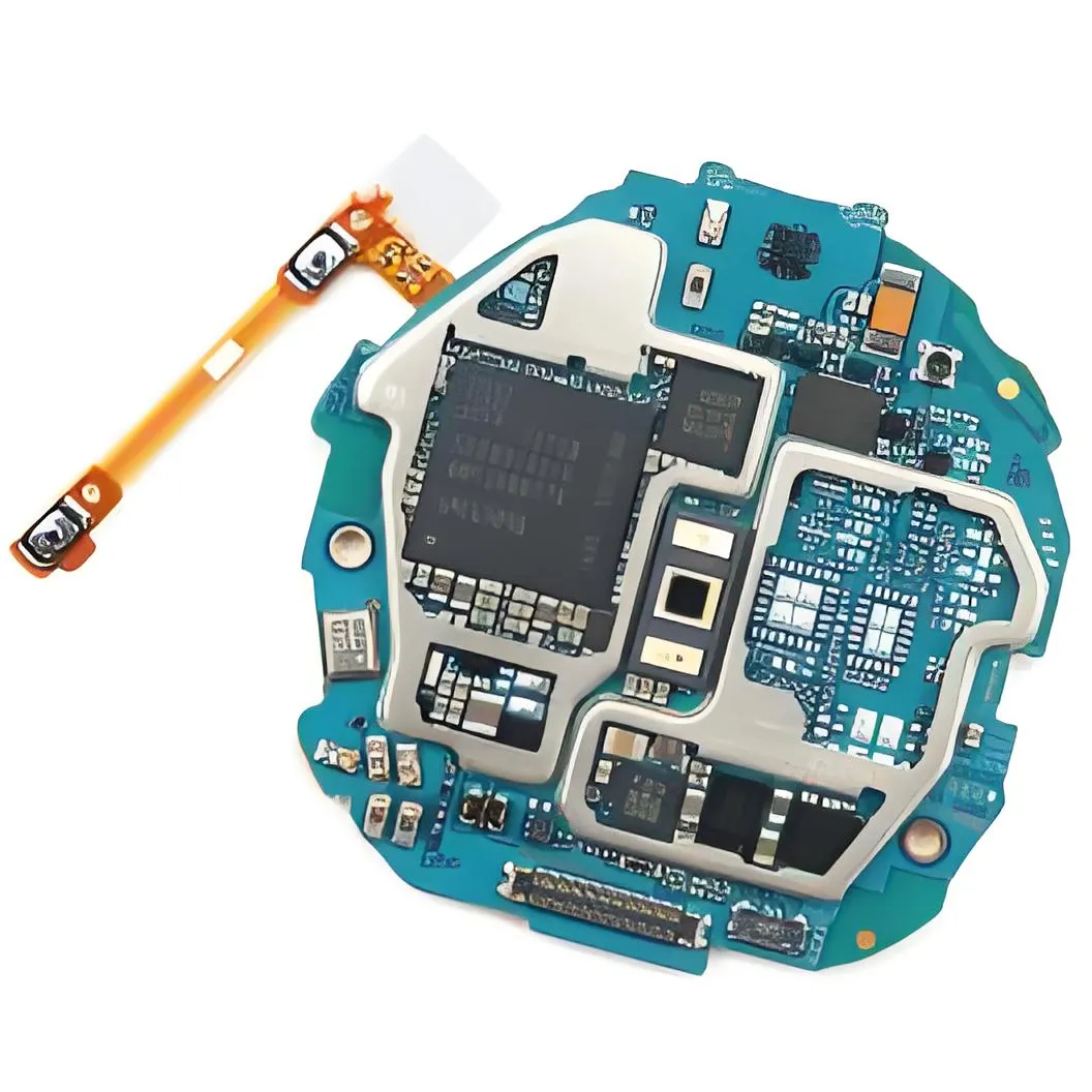
- Wearable Electronics: Devices like smartwatches and fitness trackers rely on flex PCBs to conform to curved shapes. A stencil for flex PCBs ensures precise soldering of tiny components in these compact designs.
- Medical Devices: Flexible circuitry is common in medical implants and diagnostic equipment. Accurate solder paste application using a flexible stencil PCB is critical for reliability and patient safety.
- Automotive Systems: Flex PCBs are used in sensors and control units that require durability under vibration and temperature changes. A specialized stencil helps maintain consistent assembly quality.
- Aerospace Technology: Lightweight and space-saving flex circuits are essential in satellites and aircraft. Stencils designed for flex PCBs ensure high-precision manufacturing for these critical applications.
Designing a Custom Stencil for Flex PCBs
If off-the-shelf stencils don't meet your specific needs, designing a custom stencil for handling flex circuits can be a worthwhile investment. Here's how to approach the design process:
1. Collaborate with Your PCB Manufacturer
Work closely with your PCB provider to understand the exact dimensions and material properties of your flex circuit. Share Gerber files or layout data to ensure the stencil apertures match the pad sizes and spacing, typically within a tolerance of ±10 microns for high-density designs.
2. Specify Material and Thickness
Choose a stencil material that balances durability and flexibility. Stainless steel with a thickness of 0.12mm is a common choice for flex PCB stencils, offering a good compromise between precision and adaptability to slight bends.
3. Account for Bend Areas
If your flex PCB includes specific bend zones, design the stencil to avoid placing apertures in those areas or use stepped stencils with varying thicknesses to accommodate the board's topography.
4. Test and Iterate
After receiving the custom stencil, conduct test prints on sample flex PCBs. Measure the paste volume and alignment accuracy using tools like a 3D solder paste inspection (SPI) system. Adjust the design if issues like under- or over-deposition occur.
Common Mistakes to Avoid When Handling Flex Circuits with Stencils
Even with the right tools, mistakes in circuits flex handling can lead to costly rework or defective products. Here are some pitfalls to avoid:
- Using a Rigid Board Stencil: Applying a stencil meant for rigid PCBs to a flex circuit often results in poor contact and uneven paste application. Always opt for a flexible stencil PCB designed for flex applications.
- Excessive Pressure: Applying too much squeegee pressure during printing can damage the flex PCB or distort the stencil. Stick to recommended pressure settings for your setup.
- Ignoring Storage Conditions: Flex PCBs are sensitive to humidity and temperature, which can cause them to warp before printing. Store them in a controlled environment (20-25°C, 40-60% humidity) to maintain flatness.
- Skipping Inspection: Failing to inspect the stencil or paste deposition can lead to unnoticed defects. Make post-print inspection a standard part of your workflow.
Future Trends in Stencil Technology for Flex PCBs
As the demand for smaller, more versatile electronics grows, stencil technology for flex PCBs continues to evolve. Here are some emerging trends to watch:
- Nano-Coated Stencils: These stencils feature special coatings that improve solder paste release, reducing defects even on the smallest apertures used for flex circuits.
- 3D-Printed Stencils: Advances in additive manufacturing allow for the creation of custom stencils with complex geometries tailored to unique flex PCB designs, enhancing precision in challenging areas.
- Automated Alignment Systems: New stencil printers with vision systems can automatically adjust alignment for flex PCBs, compensating for surface irregularities in real-time.
Staying updated on these advancements can help you maintain a competitive edge in manufacturing processes involving flexible circuitry.
Conclusion: Mastering Circuits Flex Handling with the Right Stencil
Handling flexible circuitry requires precision, care, and the right tools, with a PCB stencil for flex PCBs being a critical component of the process. By choosing a stencil designed specifically for flex circuits, optimizing your printing setup, and following best practices for circuits flex handling, you can achieve consistent, high-quality results in your projects. Whether you're working on wearable electronics, medical devices, or automotive systems, a flexible stencil PCB ensures that your solder paste application is accurate and reliable, paving the way for successful assembly and performance.
With the insights and tips provided in this guide, you're well-equipped to tackle the challenges of working with flex PCBs. Focus on selecting the right stencil, fine-tuning your process, and staying informed about new technologies to keep your manufacturing capabilities at the forefront of innovation.


