 ALLPCB


In the world of defense and security, military radar systems stand as critical tools for detecting threats and ensuring safety. But what powers these complex systems to perform with precision? At the heart of every radar lies advanced PCB technology, meticulously designed to ensure signal integrity, manage thermal challenges, and allow for future upgradability. In this blog, we dive deep into how PCB design intersects with military radar systems, exploring key aspects like signal integrity, thermal management, and upgradability. Whether you're an engineer or a tech enthusiast, this guide will break down the essentials of PCB technology in military applications.
The Role of Military Radar Systems in Modern Defense
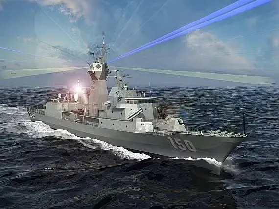
Military radar systems are indispensable for national security, used in applications ranging from air defense to missile tracking. These systems rely on radio waves to detect objects, measure distances, and even identify enemy movements. With the increasing complexity of threats, radar systems must deliver high performance under extreme conditions, whether on land, sea, or air. This is where PCB technology comes into play, acting as the backbone that supports the intricate electronics within these systems.
Why PCB Technology is Critical for Military Radar
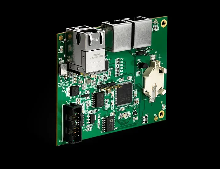
Printed Circuit Boards (PCBs) are the foundation of any electronic system, including military radar. They connect and support components like processors, transmitters, and receivers, ensuring seamless communication within the radar system. In military applications, PCBs must meet stringent requirements for reliability and durability. A failure in the PCB could mean a failure in detecting a critical threat, making the design and manufacturing of these boards a high-stakes endeavor.
PCBs in military radar systems are not just about connectivity; they are engineered to handle high-frequency signals, manage heat dissipation, and withstand harsh environments. Let’s explore how specific aspects of PCB technology address these challenges.
Signal Integrity: Ensuring Clear and Accurate Data
Signal integrity refers to the ability of a PCB to transmit signals without distortion or loss. In military radar systems, where high-frequency radio waves are processed, maintaining signal integrity is paramount. Any interference or signal degradation can result in inaccurate data, potentially missing a target or misidentifying a threat.
To achieve optimal signal integrity in PCB design for radar systems, engineers focus on several factors:
- Impedance Matching: Ensuring that the impedance of the PCB traces matches the components prevents signal reflections. For instance, a typical radar system operating at 10 GHz requires precise impedance control, often around 50 ohms, to avoid signal loss.
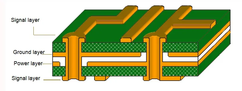
- Layer Stackup Design: Using multi-layer PCBs helps separate high-frequency signals from power and ground planes, reducing electromagnetic interference (EMI). A common setup might include 4 to 8 layers, depending on the complexity of the radar system.
- Material Selection: High-frequency laminates, such as those with low dielectric constants (Dk around 3.0 to 3.5), are often chosen to minimize signal delay and loss.
By prioritizing signal integrity, PCB technology ensures that military radar systems deliver accurate and reliable performance, even in the most demanding scenarios.
Thermal Management: Keeping Radar Systems Cool Under Pressure
Military radar systems generate significant heat due to the high power required for signal transmission and processing. Overheating can degrade components, reduce system lifespan, and even cause failures. Effective thermal management in PCB design is, therefore, a critical consideration.
Here are some strategies used in PCB technology to manage heat in military radar systems:
- Heat Sinks and Thermal Vias: Adding heat sinks to high-power components and incorporating thermal vias in the PCB helps transfer heat away from critical areas. For example, thermal vias with a diameter of 0.3 mm can be densely placed under power amplifiers to enhance heat dissipation.
- Material Choices: PCBs made from materials with high thermal conductivity, such as metal-core boards, are often used in radar applications to handle temperatures exceeding 85°C.
- Component Placement: Strategically placing heat-generating components away from sensitive areas on the PCB minimizes thermal stress. Advanced simulation tools can predict hotspots and guide layout optimization.
Effective thermal management ensures that military radar systems operate reliably, even during prolonged missions in extreme climates, from desert heat to arctic cold.
Upgradability: Future-Proofing Military Radar Systems
The rapid pace of technological advancement means that military radar systems must be adaptable to new threats and capabilities. Upgradability in PCB design allows for the integration of newer components or functionalities without requiring a complete system overhaul. This is especially important in defense, where budgets and timelines can be constrained.
PCB technology supports upgradability through:
- Modular Design: Designing PCBs with modular layouts allows specific sections to be replaced or upgraded without affecting the entire board. For instance, a radar’s signal processing module can be updated to handle higher data rates without redesigning the power supply section.
- Standardized Interfaces: Using common connectors and pin layouts ensures compatibility with future components. This approach reduces downtime during upgrades.
- Scalable Architectures: Engineers design PCBs with extra space or capacity for additional components, anticipating future needs. For example, leaving room for additional memory chips can support software updates that enhance radar algorithms.
By focusing on upgradability, PCB technology helps military radar systems stay relevant and effective over extended periods, saving resources and maintaining operational readiness.
PCB Design Challenges in Military Radar Applications
Designing PCBs for military radar systems comes with unique challenges that push the boundaries of engineering. Beyond signal integrity, thermal management, and upgradability, other considerations include:
- Harsh Environment Resistance: Military radar systems often operate in extreme conditions, from high humidity to intense vibrations. PCBs must be coated with conformal layers to protect against moisture and designed with robust mounting to withstand shocks.
- Size, Weight, and Power (SWaP) Constraints: Especially in airborne radar systems, minimizing size and weight while maintaining power efficiency is crucial. Compact PCB layouts and lightweight materials are often employed to meet these demands.
- Security: Protecting sensitive data within radar systems requires secure PCB designs that prevent tampering or reverse engineering. Techniques like embedded security chips and encrypted signal paths are increasingly common.
Addressing these challenges requires a deep understanding of both radar functionality and PCB technology, ensuring that every design decision aligns with the mission’s needs.
How PCB Technology Advances Military Radar Performance
The evolution of PCB technology has directly contributed to advancements in military radar systems. Here are a few ways this synergy drives performance:
- Higher Frequency Handling: Modern PCBs can support radar systems operating in the X-band (8-12 GHz) and beyond, enabling finer resolution for detecting smaller or stealthier targets.
- Improved Processing Speeds: With faster signal transmission on PCBs, radar systems can process data in real-time, crucial for tracking fast-moving objects like missiles. Signal speeds on high-quality PCBs can reach up to 10 Gbps in controlled environments.
- Enhanced Reliability: Military-grade PCBs undergo rigorous testing to ensure they perform under stress. Standards like MIL-PRF-31032 outline the durability requirements, ensuring PCBs can handle the toughest conditions.
These advancements mean that military radar systems are not just reactive tools but proactive assets in defense strategies, capable of anticipating and countering threats with precision.
Best Practices for Designing PCBs for Military Radar Systems
For engineers working on PCB design for military radar, adhering to best practices can make the difference between a successful system and a costly failure. Here are actionable tips:
- Prioritize Simulation: Use simulation software to model signal integrity and thermal behavior before manufacturing. Tools can predict issues like crosstalk at frequencies above 5 GHz or thermal hotspots above 100°C.
- Collaborate with Stakeholders: Work closely with radar system designers to understand specific requirements, such as power needs or frequency bands, ensuring the PCB meets all operational goals.
- Test Rigorously: Conduct environmental stress testing, including thermal cycling from -40°C to 85°C and vibration testing, to validate the PCB’s performance in real-world conditions.
- Document Thoroughly: Maintain detailed records of design choices, material selections, and test results to facilitate future upgrades or troubleshooting.
Following these practices ensures that PCB technology not only supports but enhances the capabilities of military radar systems.
Conclusion: The Future of PCB Technology in Military Radar
As military radar systems continue to evolve, so too must the PCB technology that powers them. From ensuring signal integrity to managing thermal challenges and enabling upgradability, PCBs are at the core of radar innovation. By focusing on advanced design techniques and robust materials, engineers can create systems that meet the demands of modern defense, protecting nations and saving lives.
The intersection of military radar and PCB technology is a dynamic field, ripe with opportunities for innovation. As new materials, design tools, and manufacturing processes emerge, the potential for even more powerful and reliable radar systems grows. For now, understanding the critical role of PCB design in this space is the first step toward building the defense technologies of tomorrow.





