ALLPCB


Shielding effectiveness plays a central role in controlling electromagnetic interference in electronic systems. Engineers evaluate how well materials or enclosures reduce the transmission of electromagnetic fields to maintain signal integrity and meet performance requirements. Accurate assessment relies on defined measurement techniques that distinguish between different field conditions and frequency ranges. These evaluations support reliable operation across consumer, industrial, and specialized applications.
What Is Shielding Effectiveness and Why It Matters
Shielding effectiveness quantifies the reduction in electromagnetic field strength achieved by a barrier, typically expressed in decibels. It accounts for both reflection and absorption mechanisms that limit energy passage through a material or enclosure. In practice, higher values indicate better isolation between internal circuits and external environments. This parameter directly influences compliance with electromagnetic compatibility expectations and helps prevent crosstalk or susceptibility issues in densely packed designs.
The relevance extends to printed circuit board layouts where conductive layers or enclosures must balance shielding with other mechanical and thermal constraints. Proper evaluation ensures that designs perform consistently under varying operating conditions. Without standardized measurement, comparisons between materials or configurations become unreliable.
Technical Principles Behind Shielding Effectiveness
Electromagnetic shielding operates through reflection at interfaces where impedance mismatches occur and absorption within the material volume. The total effectiveness depends on material conductivity, permeability, thickness, and the frequency of the incident field. At lower frequencies, magnetic field penetration often dominates, while higher frequencies emphasize electric field behavior and wave impedance considerations.
Measurement accuracy requires careful control of source and receiver positioning, as well as accounting for any apertures or seams that can degrade overall performance. Engineers analyze both transmitted and reflected components to isolate the contributions of each mechanism. This structured approach allows identification of whether improvements should target material properties or mechanical design features.
Near-Field and Far-Field Shielding Measurements
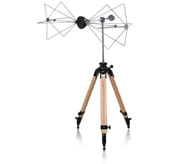
Near-field shielding measurements focus on regions close to the source where electric or magnetic fields predominate individually. These tests often employ small loop or rod antennas to assess localized performance, revealing how materials respond to non-uniform field distributions. Such evaluations prove useful during early design stages when identifying specific leakage paths on boards or within small assemblies.
Far-field shielding measurements, by contrast, examine plane-wave conditions at greater distances where the electric and magnetic components maintain a fixed relationship. These setups simulate propagation in free space and provide data more representative of system-level exposure. The distinction matters because shielding performance can differ noticeably between the two regimes, particularly for thin or layered materials.
Industry Standards Guiding Shielding Effectiveness Testing
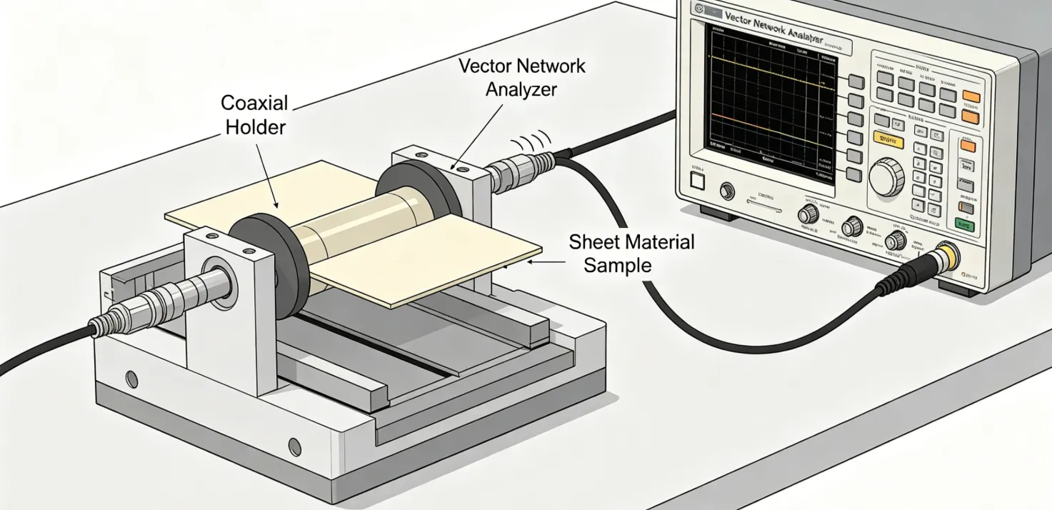
Standardized procedures ensure repeatability and comparability across laboratories and manufacturers. ASTM D4935 provides a recognized method for evaluating planar materials under far-field plane-wave conditions using a coaxial transmission line holder. The approach measures insertion loss between reference and loaded specimens over a defined frequency range, yielding net shielding effectiveness values that incorporate both reflection and absorption.
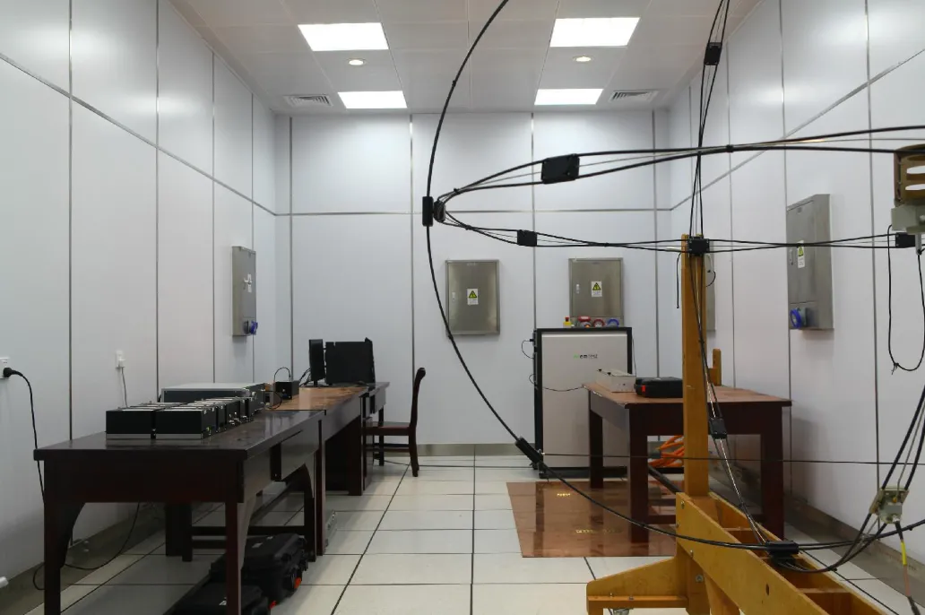
MIL-STD-285 shielding procedures address enclosure-level evaluations through coplanar source and receiver placements. These methods cover broader frequency spans and account for real-world enclosure geometries, including the effects of seams and penetrations. Consistent application of such standards supports traceable results that engineers can use for design validation and iterative improvement.
Additional guidance appears in IEC documents that outline general electromagnetic compatibility measurement frameworks applicable to shielding assessments. Selection of the appropriate standard depends on whether the focus lies on material samples or complete assemblies.
Best Practices for Reliable Measurements and Design Integration
Engineers begin by defining the frequency range and field type relevant to the application before selecting a test method. Specimen preparation must maintain uniform thickness and avoid edge effects that could skew results. Calibration of the test fixture or chamber establishes the dynamic range and confirms that the setup itself does not introduce artifacts.
During design, shielding layers integrate with grounding strategies and component placement to maximize effectiveness without compromising other performance aspects. Regular verification through prototype testing identifies discrepancies early, allowing adjustments before final production. Documentation of measurement conditions, including any deviations from standard procedures, supports future troubleshooting and compliance reviews.
Conclusion
Shielding effectiveness measurement combines fundamental electromagnetic principles with standardized test methods to deliver actionable engineering data. Distinguishing near-field and far-field conditions, applying appropriate standards such as ASTM D4935, and following structured best practices enables consistent evaluation across projects. These steps ultimately contribute to more robust electronic systems that maintain performance amid electromagnetic challenges.
FAQs
Q1: What factors influence shielding effectiveness measurement results?
A1: Material conductivity, thickness, frequency, and the distinction between near-field and far-field conditions all affect measured values. Proper fixture calibration and specimen preparation further ensure repeatability when following established procedures such as those in ASTM D4935.
Q2: How does ASTM D4935 test method support shielding effectiveness evaluation?
A2: The ASTM D4935 test method uses a coaxial transmission line to assess planar materials under far-field plane-wave conditions. It compares transmission through reference and loaded specimens to determine net shielding effectiveness across the specified frequency range.
Q3: Why are near-field shielding measurements important in addition to far-field tests?
A3: Near-field shielding measurements capture localized electric or magnetic field behavior close to sources, which can differ from plane-wave performance. These evaluations help identify specific leakage points during design refinement before system-level far-field verification.
Q4: What role does MIL-STD-285 shielding play in enclosure testing?
A4: MIL-STD-285 shielding procedures define uniform methods for measuring attenuation in enclosures across wide frequency ranges. The approach accounts for practical geometries and supports consistent assessment of complete assemblies under controlled conditions.
References
ASTM D4935-18 — Standard Test Method for Measuring the Electromagnetic Shielding Effectiveness of Planar Materials. ASTM, 2018
IEC 61000-4-21 — Testing and Measurement Techniques – Reverberation Chamber Test Methods. IEC
MIL-STD-285 — Attenuation Measurements for Enclosures, Electromagnetic Shielding. Department of Defense
IEC 50147-1 — Anechoic Chambers – Shielding Effectiveness. IEC