 ALLPCB


Marine electronics operate in environments characterized by constant exposure to saltwater, high humidity, wide temperature swings, and mechanical vibration. Selecting appropriate base materials for printed circuit boards directly influences long term reliability, signal integrity, and resistance to degradation. Engineers must evaluate thermal, electrical, and environmental properties when specifying substrates for navigation systems, communication modules, or sensor interfaces used on vessels.
Why Material Selection Matters in Marine Applications
Saltwater spray and condensation accelerate corrosion of copper traces and vias if the laminate permits moisture ingress. Temperature cycling between deck level heat and cold seawater can induce delamination or cracking when the coefficient of thermal expansion mismatches between layers. Vibration from engines and wave action adds mechanical stress that standard materials may not withstand over extended service intervals. These factors collectively drive the need for substrates with controlled moisture absorption, elevated glass transition temperatures, and stable dielectric performance across frequency ranges typical of marine radar and data links.
Key Material Properties and Engineering Considerations
Glass transition temperature, commonly abbreviated Tg, determines the point at which a polymer matrix shifts from rigid to more compliant behavior. Materials rated above 170 degrees Celsius maintain dimensional stability during soldering processes and subsequent thermal excursions encountered at sea. Moisture absorption percentage, measured under standardized humidity conditioning, indicates how much water vapor a laminate can uptake; lower values reduce the risk of conductive anodic filament formation and surface insulation resistance loss. Dielectric constant and dissipation factor influence insertion loss and phase stability in high frequency circuits such as AIS transceivers or depth sounders. Coefficient of thermal expansion in the z axis must remain compatible with copper to avoid plated through hole stress during repeated heating and cooling cycles.
Comparison of Common Substrates for Marine Use
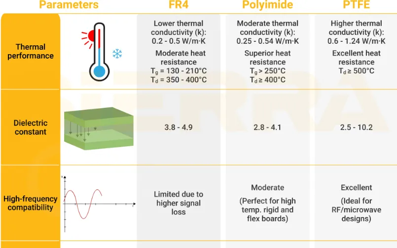
FR 4 epoxy glass laminates offer cost effective rigidity and adequate performance for many control circuits operating below 130 degrees Celsius continuous. Their moisture absorption typically ranges higher than specialty resins, making them suitable only when conformal coating and enclosure sealing provide additional protection. High Tg variants of FR 4 improve thermal endurance while retaining similar processing characteristics. Polyimide films deliver Tg values often exceeding 250 degrees Celsius along with very low moisture uptake and excellent flexibility, supporting applications where boards must conform to curved housings or endure repeated flexing from vessel motion. PTFE based composites exhibit the lowest dielectric constants and dissipation factors among common options, combined with near zero moisture absorption, making them preferable for microwave radar front ends or high speed data transmission in marine radar systems. Engineers compare these options by matching required operating temperature, frequency, and environmental exposure against measured material data sheets.
Best Practices for Material Specification and Qualification
Begin by defining the maximum continuous operating temperature, peak reflow temperature, and expected humidity exposure duration for the specific marine equipment. Reference IPC 4101 for base material property requirements when drafting procurement specifications. Select laminates that meet or exceed the minimum Tg and maximum moisture absorption thresholds established for the application class. Incorporate thermal cycling and humidity bias testing during design validation to confirm that via integrity and surface insulation resistance remain within acceptable limits after simulated marine exposure. Apply conformal coatings or potting compounds as secondary barriers, ensuring compatibility with the chosen substrate to avoid delamination at interfaces. Document all material choices and qualification results to support traceability required under quality management systems such as ISO 9001.

Quality Control and Standards Compliance
Incoming material inspection verifies laminate thickness, copper weight, and Tg through differential scanning calorimetry or thermomechanical analysis. During fabrication, adherence to IPC 6012 ensures that finished boards meet performance specifications for rigid printed boards, including requirements for plated through hole quality and dielectric spacing. Acceptability criteria outlined in IPC A 600 guide visual and microscopic evaluation of etch quality, solder mask coverage, and surface finish integrity. These standards collectively reduce the likelihood of field failures attributable to material or process deficiencies.
Conclusion
Proper selection of marine grade PCB materials begins with a clear understanding of environmental stresses and required electrical performance. High Tg formulations, polyimide, and PTFE each address specific combinations of temperature, moisture, and frequency demands encountered in marine service. Systematic comparison against measured properties, followed by qualification testing aligned with IPC standards, provides the engineering basis for reliable long term operation. Procurement and design teams that follow these structured evaluations achieve higher first pass yields and reduced warranty exposure in demanding saltwater environments.
FAQs
Q1: What defines marine grade PCB materials?
A1: Marine grade PCB materials are laminates selected for low moisture absorption, elevated Tg, and stable electrical properties under saltwater, humidity, and thermal cycling conditions typical of shipboard electronics. They support reliable operation of navigation, communication, and sensor systems exposed to harsh marine environments.
Q2: When should engineers specify high Tg PCB materials for marine projects?
A2: High Tg PCB materials become necessary when continuous operating temperatures exceed 130 degrees Celsius or when boards experience repeated soldering and thermal excursions during vessel maintenance cycles. They maintain rigidity and via integrity better than standard Tg resins under these conditions.
Q3: What are the primary advantages of polyimide PCB marine applications?
A3: Polyimide offers high thermal stability, low moisture uptake, and flexibility that accommodates vibration and curved mounting surfaces common in marine electronics. These characteristics reduce delamination risk and support long service life in saltwater environments.
Q4: How does PTFE PCB marine performance compare with FR 4 in high frequency circuits?
A4: PTFE provides significantly lower dielectric constant and dissipation factor than FR 4, resulting in reduced signal loss for radar and high speed data links. Combined with minimal moisture absorption, PTFE maintains consistent electrical performance where FR 4 may exhibit drift under prolonged humidity exposure.





