 ALLPCB


What Is PTH Drilling and Why It Matters
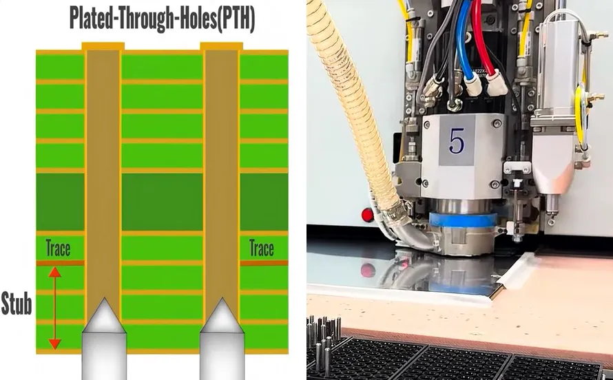
Plated through-hole drilling creates vertical interconnects by first drilling holes through the entire PCB laminate stack and then depositing copper on the hole walls. This method remains essential for boards that require robust mechanical attachment of components or high-current paths that surface traces alone cannot support. In contrast to blind or buried vias, PTHs span all layers and provide straightforward routing options during layout. Industry standards such as IPC-6012E define the qualification criteria for these features to guarantee long-term reliability under thermal and mechanical stress. Engineers who specify PTH parameters early in the design cycle reduce the risk of field failures and costly redesigns.
Technical Principles of PTH Drilling
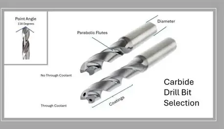
The drilling operation uses rotating carbide or coated tools to remove material at controlled feed rates and spindle speeds. Entry and exit materials protect the laminate surfaces while the drill bit penetrates copper foils and resin systems. Heat generated during cutting can smear resin along the hole wall, which must be addressed before plating. Drill bit selection depends on laminate type, hole diameter, and stack thickness, with larger diameters requiring more robust geometries to maintain straightness.
Drilling speed PTH parameters balance material removal rate against tool life and hole quality. Excessive speed produces excessive heat that degrades hole wall integrity, while insufficient speed leads to poor chip evacuation and increased torque. Feed rate and peck cycles further refine the process for thicker boards. After drilling, the desmear process removes resin smear and exposes glass fibers or copper for reliable adhesion of the subsequent electroless copper layer.
Common drilling defects include nail heading, where copper is pushed outward at the hole entrance, and resin recession that creates voids after plating. Hole wall roughness, taper, and breakout at the exit side also affect plating uniformity and electrical performance. These issues arise from improper parameter selection, worn tooling, or mismatched entry materials.
Best Practices for PTH Drilling Techniques
Engineers should collaborate with fabricators during the design phase to select hole sizes that match available tooling and stack-up constraints. Minimum annular ring requirements and copper weights influence the final drilled diameter, so designers account for plating thickness when defining finished hole sizes. Drill bit selection favors tools with optimized point angles and flute designs matched to the specific resin system and copper thickness.
Maintaining consistent drilling speed PTH settings across similar jobs improves process control and reduces variation. Peck drilling cycles help clear debris in deeper holes, while vacuum systems and proper coolant delivery minimize heat buildup. The desmear process typically combines chemical swelling and permanganate etching to achieve uniform surface activation without excessive fiber protrusion.
Process monitoring includes periodic inspection of hole quality using cross-section analysis and automated optical inspection. Statistical process control tracks parameters such as positional accuracy and diameter tolerance to maintain compliance with IPC-A-600K acceptability criteria. When defects appear, root-cause analysis focuses on tool wear, spindle runout, or laminate material lot variation rather than isolated adjustments.
Practical Considerations for Electrical Engineers
Design rules should incorporate sufficient clearance around PTHs to accommodate drill wander and plating buildup. High-aspect-ratio holes demand tighter control of drilling parameters and may require alternative entry materials or reduced feed rates. Thermal management considerations arise when PTHs carry significant current, prompting evaluation of copper plating thickness and via fill options where needed.
Troubleshooting begins with reviewing the drill program and tool life data when positional or diameter issues surface. Collaboration with the fabricator on laminate selection can mitigate resin smear tendencies in high-Tg materials. Regular communication of expected volumes and quality targets helps align manufacturing processes with design intent.
Conclusion
Effective PTH drilling combines precise mechanical operations with controlled chemical preparation to deliver reliable vertical interconnects. Electrical engineers who understand drill bit selection, drilling speed PTH optimization, the desmear process, and common drilling defects can specify boards that meet both electrical and mechanical requirements. Adherence to established industry standards supports consistent quality across production runs. Implementing these techniques early in the design workflow minimizes iterations and supports robust product performance.
FAQs
Q1: What are the key PTH drilling techniques used in multilayer PCB fabrication?
A1: PTH drilling techniques center on controlled mechanical removal of laminate material followed by surface preparation for metallization. Parameters such as spindle speed, feed rate, and peck depth are adjusted according to board thickness and material properties. The subsequent desmear process ensures clean hole walls for uniform copper deposition. These steps collectively determine the electrical and mechanical integrity of the finished interconnects.
Q2: How does drill bit selection affect PTH quality and reliability?
A2: Drill bit selection influences hole straightness, wall roughness, and positional accuracy. Carbide tools with appropriate geometries reduce heat generation and improve chip evacuation for the target laminate system. Matching bit diameter and point design to the stack-up minimizes defects such as nail heading or exit-side breakout. Proper selection extends tool life and supports tighter tolerances required by high-density designs.
Q3: Why is drilling speed PTH an important parameter to control?
A3: Drilling speed PTH directly impacts heat generation, tool wear, and hole wall quality. Optimal speeds balance material removal efficiency with the prevention of resin smear and copper deformation. Combined with appropriate feed rates, controlled speed reduces the occurrence of drilling defects that compromise plating adhesion. Fabricators monitor these parameters to maintain consistency across production lots.
Q4: What role does the desmear process play after PTH drilling?
A4: The desmear process removes resin residue from the hole wall and exposes reinforcement fibers or copper surfaces for reliable electroless plating. Chemical or plasma methods achieve uniform activation while preserving hole geometry. Inadequate desmear leads to voids or weak adhesion that degrade electrical performance over time. Proper execution supports compliance with acceptance criteria defined in relevant IPC standards.
References
IPC-6012E — Qualification and Performance Specification for Rigid Printed Boards. IPC, 2017
IPC-A-600K — Acceptability of Printed Boards. IPC, 2020
ISO 9001:2015 — Quality Management Systems. ISO, 2015


