 ALLPCB


Overview
In some applications, supercapacitors are emerging as potential alternatives to chemical batteries for energy storage. Their primary advantages, however, must be balanced against several significant drawbacks.
Advantages and limitations
Supercapacitors have very long cycle life—on the order of 10,000,000 charge/discharge cycles—and can be charged and discharged at very high currents, exceeding 1,000 A in some cases. They are also largely insensitive to temperature variations. On the downside, they cannot match batteries in energy density or cost: supercapacitors typically provide only about 3–5% of the energy density of lithiumion cells while costing 10 to 15 times more.
Key design challenges
In certain applications the advantages outweigh these limitations. Even so, supercapacitors present two major design challenges related to charging and energy recovery. The first is how to transfer energy into a capacitor that is effectively a short circuit when fully discharged. The second is how to recover energy as the capacitor is used and its voltage approaches 0 V. Overcoming these two issues is a primary obstacle to replacing batteries with supercapacitors.
Charging losses with linear chargers
Linear chargers dissipate a large portion of available energy when charging a fully discharged capacitor. As the capacitor charges, the fraction of energy lost decreases and a greater portion is stored in the capacitor. Considering both the power absorbed by the capacitor and the power dissipated in the charger, a linear charger can dissipate more than half of the available charging energy as heat over the full cycle. In practice, linear chargers may discard around 58% of the available charging energy as heat.
SMPS charging approach
An alternative is a switching-mode power supply (SMPS) approach, where the voltage difference between the source and the output capacitor is dropped across an inductor. In a voltage-regulation SMPS design, the inductor current is driven by the difference between the voltage across the output capacitor and a fixed reference voltage. That error voltage is amplified, integrated, phase-shifted, and fed back to a pulse-width-modulation (PWM) comparator.
The PWM comparator uses this signal to determine the amount of current that will flow through the inductor in the next switching period. With careful design, SMPS circuits can achieve conversion efficiencies in the range of 80–90%.
Optimizing energy transfer during charging
In charger circuits, the time spent at a constant output voltage is typically short. By definition, charger circuit design must perform most of the work while raising the capacitor voltage from zero to the final voltage. Therefore, energy transfer must be optimized during the charging interval.
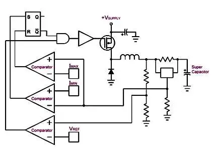
A practical charging circuit needs to regulate capacitor charging current independently of the output voltage, using voltage feedback only to determine when charging is complete. One variation of a typical SMPS design achieves this by comparing the inductor current to two fixed thresholds to regulate current: one at the desired current level and the other at a lower threshold. Initially, because the voltage across the inductor is relatively high, the time for the inductor current to rise from the lower threshold to the desired current is short. The discharge interval is correspondingly longer because the inductor must discharge down to a relatively small voltage. As the capacitor accumulates charge, the voltage difference decreases, increasing the current ramp-up time while the capacitor voltage rises and the discharge interval shortens.
Implementation considerations
Similar behavior can be implemented with a conventional time-based PWM drive, but the choice of inductor is critical to maintaining the intended current levels. Instability may also appear when the duty cycle exceeds 50%. A simple way to avoid this instability is to use a relaxation-style oscillator or 555-timer-style system that employs two comparators and an SR latch so that the inductor and associated component values set the switching frequency.


