 ALLPCB


Introduction
Power electronics systems, such as inverters, converters, and motor drives, operate under high current and voltage conditions that generate significant heat. This heat buildup poses risks to component reliability, system efficiency, and overall lifespan if not managed properly. Metal core printed circuit boards, or MCPCBs, emerge as a key solution for thermal management in PCBs, particularly in demanding applications like power supplies. These boards leverage a metallic base to enhance heat dissipation, allowing power devices like MOSFETs and IGBTs to maintain safe operating temperatures. Factory-driven insights reveal that integrating MCPCBs early in high-power PCB design prevents common failures such as delamination or solder joint cracking. This guide explores the principles, applications, and best practices for using MCPCBs to address these thermal challenges effectively.
What Are MCPCBs and Why Do They Matter in Power Electronics?
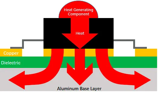
MCPCBs consist of a solid metal core, typically aluminum or copper, bonded to a thin dielectric layer and topped with a copper circuit layer. This construction differs from standard FR4 boards by providing a low thermal resistance path directly from heat-generating components to the board's exterior. In power electronics, where devices handle kilowatts of power, standard PCBs struggle with heat spreading due to their poor in-plane thermal conductivity. MCPCBs excel in thermal management in PCBs by conducting heat through the core, which can then be dissipated via heatsinks or chassis mounting. Their relevance grows in sectors like renewable energy systems and electric vehicles, where compact designs demand superior heat dissipation PCB capabilities.
The importance of MCPCBs stems from the escalating power densities in modern electronics. Factory processes for MCPCBs ensure uniform metal thickness and dielectric integrity, aligning with performance specifications that prevent warping under thermal stress. Without such boards, engineers face elevated junction temperatures that accelerate electromigration and reduce mean time between failures. Adopting MCPCBs for power supplies enables reliable operation at higher currents, optimizing system performance. These boards also support multilayer configurations for complex high-power PCB design, balancing electrical isolation with thermal efficiency.
Thermal Challenges in Power Electronics PCB Design
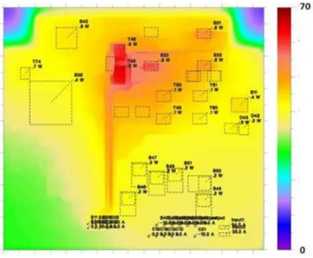
Power electronics generate heat primarily through conduction losses in switches, switching losses in semiconductors, and resistive losses in traces. These sources create localized hotspots that propagate via conduction, convection, and radiation, often exceeding component ratings. In standard PCBs, thin copper layers and organic substrates limit heat spreading, leading to temperature gradients that stress solder joints and vias. High-power applications amplify these issues, as continuous operation at hundreds of amps causes board-level temperatures to rise rapidly. Poor thermal management results in derating components, reduced efficiency, and potential safety hazards like thermal runaway.
Factory observations highlight challenges such as CTE mismatch between layers, which induces mechanical stress during temperature cycling. Convection alone proves insufficient in enclosed housings typical of power supplies, necessitating conductive paths. Radiation contributes minimally at PCB scales, underscoring the need for enhanced conduction. Engineers must model these effects early to predict hotspots and ensure compliance with reliability standards. Addressing these upfront prevents costly redesigns and field failures in demanding environments.
Technical Principles of Heat Dissipation in MCPCBs
Heat dissipation in MCPCBs relies on the high thermal conductivity of the metal core, which spreads heat laterally and vertically far better than FR4 substrates. The core acts as a heat sink within the board, lowering thermal resistance from component pads to the mounting surface. Dielectric layers, engineered for thinness and moderate conductivity, minimize impedance to heat flow while maintaining electrical isolation. This setup follows design guidelines outlined in IPC-2221, which emphasize material selection for thermal performance in high-power PCB design. Conduction dominates, with Fourier's law governing the heat flux proportional to the temperature gradient and material conductivity.
Multilayer MCPCBs incorporate thermal vias to bridge insulating layers, channeling heat to the core efficiently. Factory lamination processes control bond line thickness to optimize this path, reducing overall thermal impedance. Compared to standard boards, MCPCBs achieve more uniform temperature distribution, critical for densely packed power devices. Radiation and convection enhance dissipation when paired with external cooling, but the core's role remains primary. Simulations validate these principles, showing significant junction temperature reductions in MCPCB applications.
MCPCB Applications in Power Electronics
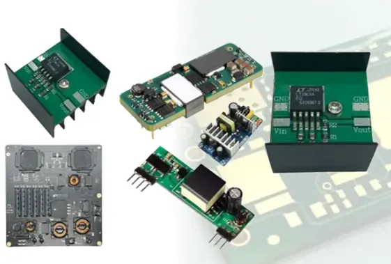
MCPCBs find extensive use in power supplies, where rectifiers and switching regulators demand robust thermal management in PCBs. In DC-DC converters, they support high-frequency operation by keeping switching devices cool, preventing efficiency drops. Motor drives benefit from MCPCBs' rigidity and heat spreading, ideal for IGBT modules under variable loads. Industrial power equipment, including UPS systems and inverters, leverages these boards for their ability to handle transient thermal spikes. Factory production scales these designs with precise core machining, ensuring repeatability across volumes.
In automotive and aerospace power electronics, MCPCBs enable compact layouts without compromising heat dissipation PCB performance. Their mechanical strength resists vibration-induced fatigue, complementing thermal benefits. High-power PCB design in these fields prioritizes MCPCBs for edge-mounted heatsinks, maximizing conduction to chassis. Applications extend to telecom power units, where reliability under continuous load is paramount. Overall, MCPCBs transform thermal-limited designs into reliable systems.
Best Practices for High-Power PCB Design with MCPCBs
Start with component placement directly over the metal core to minimize thermal path lengths, aligning pads with high-conductivity zones. Use wide traces and polygons to distribute current evenly, reducing I-squared-R losses as per IPC-2221 guidelines. Incorporate thermal vias under hotspots, filled or tented to enhance conduction without compromising solderability. Factory recommendations include specifying core thickness based on power levels, typically 1 to 2 mm for standard applications. Pair MCPCBs with external heatsinks using thermal interface materials for optimal stack-up performance.
Layer stacking merits careful planning: position power planes adjacent to the core, insulating signal layers outward. Simulate thermal profiles using finite element analysis to iterate layouts before fabrication. Avoid splitting the core under critical components to maintain continuous heat spreading. For multilayer designs, embed vias strategically to funnel heat downward. Adherence to IPC-6012 performance specifications ensures boards withstand thermal cycling without defects.
Control impedance in high-power traces while prioritizing width for low resistance. Factory-driven best practices involve edge plating or slots for heatsink contact, improving dissipation. Test prototypes under load to validate models, adjusting via density as needed. These steps yield MCPCBs optimized for power electronics, balancing thermal, electrical, and mechanical demands.

Troubleshooting Common Issues in MCPCB Implementations
Overheating despite MCPCBs often traces to inadequate via thermal mass or dielectric delamination from CTE mismatch. Inspect for voids in the core bond using ultrasonic testing, addressing via reflow processes. Warpage from asymmetric heating requires balanced copper distribution across layers. Factory insights suggest annealing the core pre-lamination to stabilize dimensions. Solder joint reliability improves with controlled ramp rates during reflow, preventing core distortion.
Hotspot migration signals poor current sharing; widen polygons and add stitching vias. If chassis coupling fails, verify interface pressure and gap filler application. Simulations help isolate issues, correlating to thermal camera data. These troubleshooting steps, grounded in standard qualification tests, extend MCPCB lifespan in high-power environments.
Conclusion
MCPCBs provide a proven pathway to conquer thermal challenges in power electronics, offering superior heat dissipation PCB capabilities essential for modern designs. By leveraging their conductive cores and adhering to best practices like strategic via placement and IPC-guided layouts, engineers achieve reliable high-power PCB design. Applications in power supplies and beyond demonstrate their versatility, from steady-state loads to transients. Factory-aligned production ensures these boards meet performance demands without compromise. Integrating MCPCBs not only mitigates risks but elevates system efficiency and longevity.
FAQs
Q1: What makes MCPCBs ideal for thermal management in PCBs for power supplies?
A1: MCPCBs feature a metal core that conducts heat away from components more effectively than FR4, reducing junction temperatures in high-power scenarios. This structure supports direct mounting to heatsinks, enhancing overall dissipation. Factory processes ensure dielectric integrity for electrical safety. Engineers benefit from uniform heat spreading, critical for MCPCB applications in converters and regulators.
Q2: How does high-power PCB design benefit from MCPCBs?
A2: High-power PCB design gains from MCPCBs' low thermal resistance, allowing denser layouts without derating. Thermal vias and wide traces optimize current paths alongside heat flow. Standards like IPC-2221 guide material and layout choices for reliability. These boards handle elevated currents in motor drives, preventing failures from hotspots.
Q3: What are key strategies for heat dissipation PCB using MCPCBs?
A3: Key strategies include placing power devices over the core, using via arrays for interlayer transfer, and ensuring robust heatsink interfaces. Balanced copper distribution minimizes warpage. Simulations predict performance pre-production. MCPCBs for power supplies excel here, supporting continuous high-load operation reliably.
Q4: Can MCPCBs handle multilayer high-power designs?
A4: Yes, multilayer MCPCBs manage heat in complex high-power designs by channeling it through the core via embedded vias. Insulation layers maintain isolation while thin dielectrics aid conduction. Factory lamination controls thickness for consistency. This suits advanced thermal management in PCBs for inverters.
References
IPC-2221B — Generic Standard on Printed Board Design. IPC, 2012
IPC-6012E — Qualification and Performance Specification for Rigid Printed Boards. IPC, 2015
IPC-A-600K — Acceptability of Printed Boards. IPC, 2020


