 ALLPCB


Introduction
In low volume PCB assembly projects, engineers often face tight budgets and short timelines that make every component choice critical. Solder paste stencils play a central role in applying consistent deposits across pads, yet the decision between frameless and framed options directly influences overall PCB manufacturing costs. Frameless stencils eliminate the rigid aluminum frame found in traditional designs, which reduces upfront material and shipping expenses while still delivering acceptable print quality when paired with appropriate tensioning hardware. This approach supports stencil amortization over smaller batch sizes without forcing teams to absorb the full framed stencil cost on every run. Practical experience shows that frameless solutions work well when production volumes stay below a few hundred boards, provided process controls remain tight.
What Is a Frameless Stencil and Why It Matters
A frameless stencil consists of a thin metal foil, typically stainless steel, that contains laser-cut apertures matching the PCB pad layout. Unlike framed versions, it arrives without a surrounding border and relies on a separate tensioning system or reusable frame during use. This construction lowers the frameless stencil cost compared with a complete framed stencil cost because the frame itself represents a significant portion of the total price. For low volume PCB assembly, the savings become meaningful when only a handful of boards require paste printing, allowing faster turnaround without committing capital to permanent tooling. Engineers in procurement and design roles appreciate the flexibility, as the same foil can sometimes be reused across similar layouts if aperture patterns align closely enough. The approach aligns with standard practices that emphasize cost control while maintaining deposit volume consistency.
Technical Principles of Frameless Stencil Performance
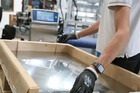
The printing mechanism depends on controlled tension applied across the foil to keep it flat against the PCB surface during squeegee travel. Proper tension prevents foil lift-off at the edges, which could otherwise cause incomplete paste transfer or bridging. In low volume PCB assembly environments, operators typically mount the foil in a universal tensioning frame that clamps the perimeter and stretches the material evenly. This setup compensates for the absence of a factory-installed frame yet introduces an extra handling step that must be executed consistently to avoid warpage or misalignment.

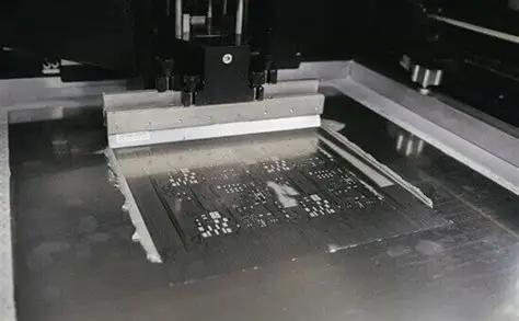
Deposit height and volume remain governed by aperture geometry and foil thickness, factors unchanged by the presence or absence of a frame. When tension is applied correctly, print results meet the same acceptance criteria used for framed stencils in most production settings. Troubleshooting often centers on verifying uniform tension before each run and confirming that the PCB support tooling holds the board flat, because any board warpage amplifies the risk of poor contact.
Practical Solutions and Best Practices for Low-Volume Use
Teams evaluating frameless stencil cost versus framed stencil cost should first calculate expected board count and determine whether the frame expense can be amortized effectively. For runs under 200 boards, the lower initial outlay of a frameless option frequently yields measurable PCB manufacturing costs reduction, especially when combined with quick-turn foil ordering. Best practice begins with selecting foil thickness and aperture reduction percentages that match the component mix, then validating the chosen parameters on a test print before committing the full batch.
Operators should establish a repeatable mounting sequence for the tensioning hardware, including torque checks on clamps and visual inspection for foil flatness. When switching between multiple PCB designs, keeping a library of pre-tensioned setups or quick-change adapters helps maintain throughput. Documentation of each print run, including tension settings and observed defects, supports continuous improvement and reduces repeat issues in subsequent low volume PCB assembly jobs. Regular cleaning of the foil and inspection for aperture wear further protect print quality without adding significant overhead.
Related Reading: Framed vs. Frameless Stencils: Understanding the Pros and Cons for SMT Assembly
Process Controls and Troubleshooting Insights
Maintaining consistent results with frameless stencils requires attention to support tooling and environmental factors. Insufficient board support can allow flexing under squeegee pressure, leading to smeared deposits or incomplete release. Engineers address this by using dedicated fixtures or adjustable pins that match the specific PCB outline. Temperature and humidity fluctuations in the print area can also affect paste rheology, so monitoring these conditions helps stabilize volume across boards.
When bridging or insufficient paste appears, the first checks focus on tension uniformity and squeegee angle rather than stencil design itself. Adjusting print speed or adding a slight snap-off distance often resolves release problems without altering the foil. These targeted adjustments keep low volume PCB assembly lines running efficiently while controlling overall PCB manufacturing costs.
Related Reading: Troubleshooting Common Issues with Frameless Stencils in PCB Assembly
Conclusion
Frameless stencils offer a practical route to lower frameless stencil cost in low volume PCB assembly without sacrificing the core requirements of accurate solder paste deposition. By removing the frame expense, teams achieve better stencil amortization across limited board counts and reduce total PCB manufacturing costs when volumes do not justify permanent framed tooling. Success depends on disciplined tensioning practices, proper support tooling, and adherence to established process controls. Engineers who incorporate these considerations early in project planning can balance quality, speed, and budget effectively.
FAQs
Q1: How does frameless stencil cost compare with framed stencil cost for small production runs?
A1: Frameless options eliminate the frame material and fabrication steps, resulting in a noticeably lower purchase price that improves stencil amortization when board quantities remain modest. In low volume PCB assembly, this difference often translates into meaningful savings on total PCB manufacturing costs, provided the added tensioning step integrates smoothly into existing workflows.
Q2: When should engineers choose frameless stencils for low volume PCB assembly?
A2: Selection makes sense when expected volumes fall below a few hundred boards and the project timeline favors rapid, lower-cost tooling. The approach supports quick design iterations while keeping PCB manufacturing costs under control, although it requires consistent operator training on tensioning procedures.
Q3: What factors influence successful stencil amortization with frameless designs?
A3: Amortization improves when the same foil can serve multiple similar layouts or when tensioning hardware is reused across projects. Careful tracking of print quality and foil condition helps extend usable life, directly lowering the effective cost per board in low volume PCB assembly.
Q4: How do process controls affect overall PCB manufacturing costs when using frameless stencils?
A4: Robust controls on tension, support tooling, and paste parameters reduce defects and rework, which protects the cost advantage of the frameless approach. Consistent documentation and preventive maintenance further stabilize results without introducing hidden expenses.
References
IPC-7525B — Stencil Design Guidelines. IPC, 2012
J-STD-001H — Requirements for Soldered Electrical and Electronic Assemblies. IPC, 2020
IPC-A-610G — Acceptability of Electronic Assemblies. IPC, 2017


