 ALLPCB


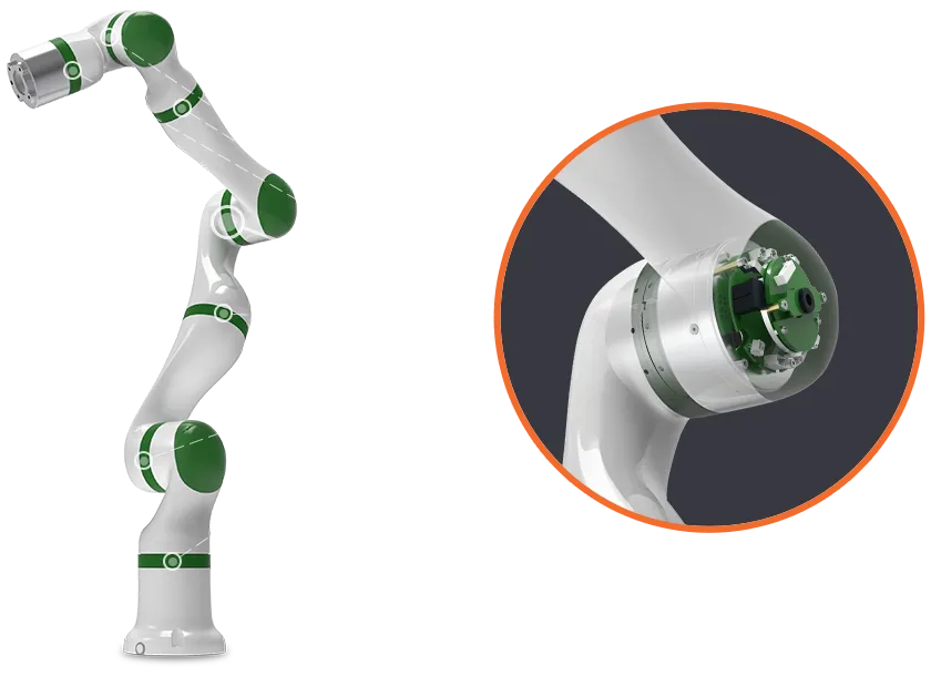
Flexible printed circuit boards enable compact and adaptable electronics in robotic systems. These circuits support continuous movement while maintaining reliable electrical connections. Engineers select flex PCBs when rigid boards cannot accommodate the required motion or space constraints in robotic arms, joints, and sensor arrays. The technology integrates multiple functions into a single assembly that withstands repeated flexing without performance loss.
What Are Flexible PCBs and Why They Matter in Robotics
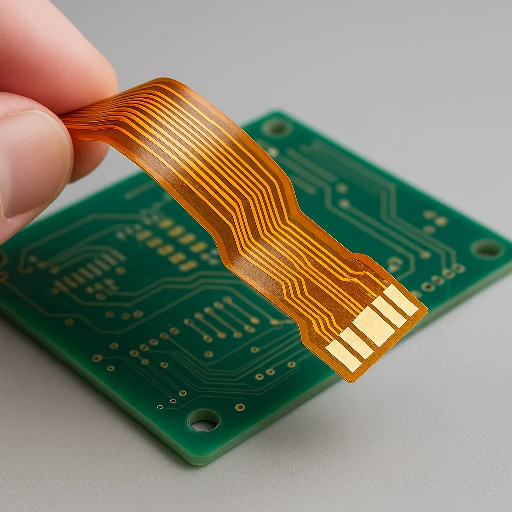
A flexible PCB consists of thin dielectric layers, typically polyimide, with copper conductors patterned on one or more sides. Unlike rigid boards, flex circuits bend and twist during operation. In robotics control applications, this capability allows circuits to follow the motion of moving parts such as grippers or rotating joints. The small form factor reduces overall system weight and volume, which improves robot speed and energy efficiency. Sensor integration becomes straightforward because traces can route directly to strain gauges, encoders, and temperature sensors mounted on moving surfaces. Interconnect solutions simplify wiring harnesses by replacing discrete cables with continuous flexible circuits that maintain signal integrity across dynamic interfaces.
Technical Principles of Flexible PCB Design for Robotics Control
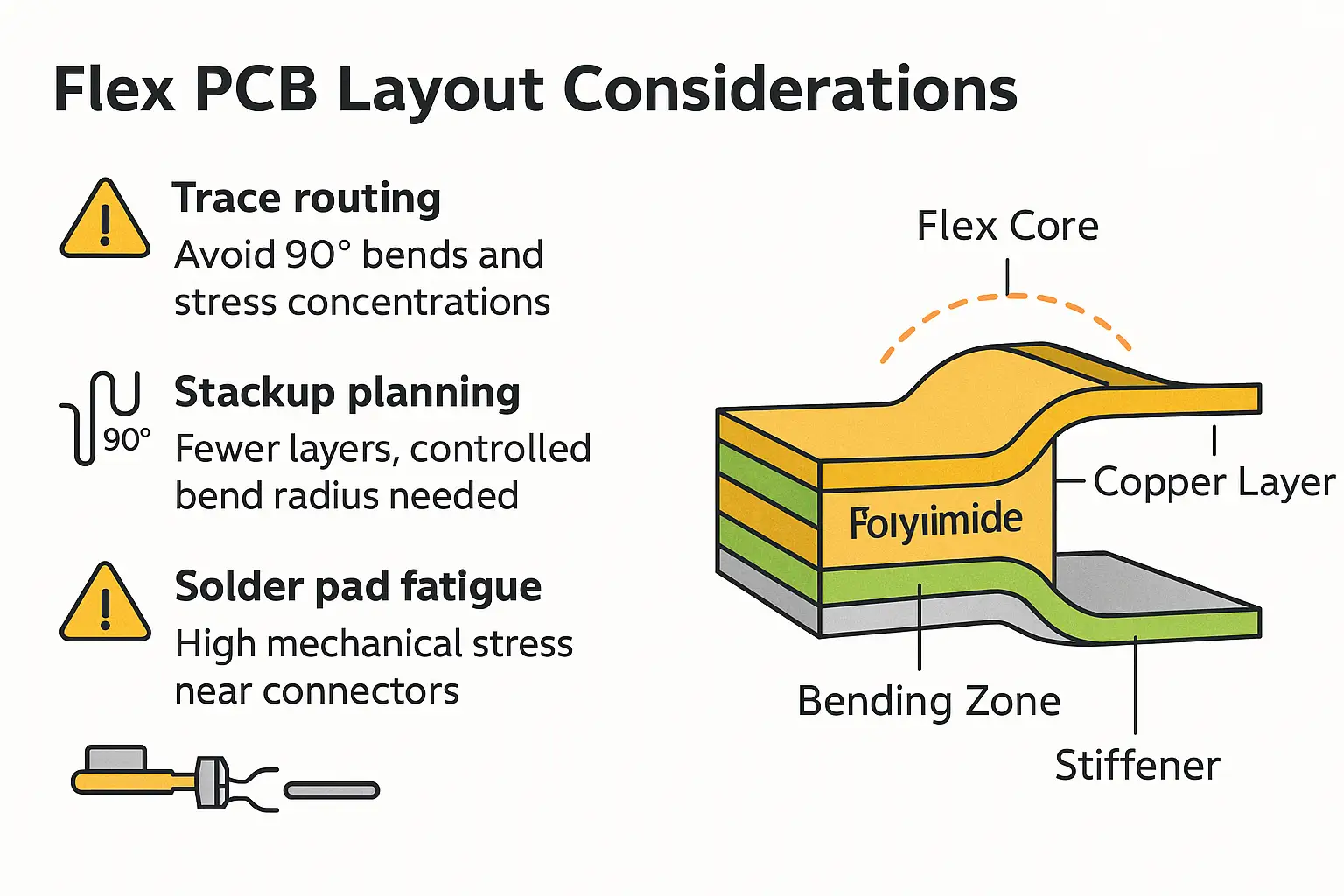
Design begins with selection of base materials that balance flexibility and electrical performance. Polyimide films provide high thermal stability and low moisture absorption, supporting operation across wide temperature ranges typical in industrial robotics. Copper foil thickness and trace geometry determine current-carrying capacity and resistance to fatigue during repeated bending. Engineers calculate minimum bend radius based on the number of layers and copper weight to prevent cracking of conductors or delamination of coverlays. Dynamic bending applications require additional attention to strain relief features and neutral-axis positioning of critical traces. Signal integrity analysis accounts for changes in impedance that occur when the circuit flexes, ensuring consistent performance for high-speed control signals. Via placement avoids high-stress zones, and tear-drop reinforcements strengthen connections at pad-to-trace transitions. These principles align with established design guidelines that specify layout rules for reliable flex circuits.
Design Considerations and Best Practices for Robotics Applications
Effective robotics PCB design starts with a thorough mechanical analysis of the robot's motion envelope. Engineers map expected bend angles, cycle counts, and environmental exposures before finalizing stackup and routing. Traces run perpendicular to the bend axis where possible, and ground planes incorporate hatched patterns to reduce stiffness. Stiffeners added at connector or component areas provide support without compromising overall flexibility. Sensor integration benefits from localized rigid sections created by additional layers or bonded reinforcements, allowing surface-mount devices to remain stable during motion. Interconnect solutions often combine flex circuits with zero-insertion-force connectors or direct soldering to rigid boards, minimizing points of failure. Thermal management incorporates copper pours or embedded heat-spreading layers when power devices reside on the flex section. Prototyping includes accelerated flex testing to validate the design against expected operational cycles. These practices produce robust assemblies that maintain electrical continuity and mechanical integrity throughout the robot's service life.
Challenges in Implementation and Mitigation Strategies
Repeated flexing introduces mechanical stress that can lead to conductor fatigue or coverlay cracking over time. Mitigation involves optimizing trace width, spacing, and routing direction relative to the bend axis. Environmental factors such as dust, moisture, and temperature cycling require appropriate coverlay materials and edge sealing. Electromagnetic interference increases when circuits move near motors or power lines, addressed through strategic ground plane design and shielding layers. Assembly processes must accommodate the flexible nature of the board during component placement and soldering to avoid unintended creasing. Quality verification includes visual inspection, electrical testing, and sample flex cycling before full production release. These steps reduce field failures and support consistent performance in demanding robotics environments.
Conclusion
Flexible PCBs deliver essential capabilities for modern robotics control by combining compact size, dynamic movement tolerance, and reliable sensor and interconnect integration. Careful attention to material selection, bend geometry, and stress mitigation produces designs that meet the rigorous demands of continuous operation. Following structured engineering practices ensures that flex circuits contribute to lighter, faster, and more capable robotic systems without compromising reliability.
FAQs
Q1: What advantages does a flexible PCB offer in robotics PCB design compared with rigid boards?
A1: Flexible circuits accommodate continuous motion in robotic joints and arms while maintaining electrical connections. They reduce weight and volume, support direct sensor integration, and simplify interconnect solutions by eliminating bulky cable harnesses. These characteristics improve overall robot performance and reliability in dynamic environments.
Q2: How does dynamic bending affect trace layout in flex PCB designs for robotics?
A2: Dynamic bending requires traces to run perpendicular to the primary flex axis and avoid sharp corners that concentrate stress. Engineers position critical signals near the neutral axis and incorporate strain relief features. Proper layout prevents fatigue failures and maintains signal integrity across thousands of motion cycles.
Q3: What role does sensor integration play in flexible PCB applications for robotic control?
A3: Sensor integration allows strain, position, and temperature data to be collected directly at moving points without additional wiring. Flexible circuits route signals from these sensors back to the main controller while following the robot's motion. This approach improves response time and reduces points of mechanical failure.
Q4: Which industry standards guide the design of flexible PCBs used in robotics?
A4: Design practices follow IPC-2223 guidelines for sectional design of flexible printed boards. Qualification and performance requirements reference IPC-6013 specifications for flexible printed boards. These documents provide consistent criteria for materials, construction, and testing that support reliable robotics applications.


