 ALLPCB


Introduction
In surface mount technology assembly, precision alignment is critical, especially when handling fine-pitch components such as BGAs and QFPs. Panel fiducial techniques provide the reference points that automated pick-and-place machines rely on to achieve sub-millimeter accuracy across entire panels of multiple boards. As designs incorporate denser layouts with pitches below 0.5 mm, even minor misalignments can lead to soldering defects, yield losses, and rework costs. This article explores advanced panel fiducial techniques, their role in overcoming SMT assembly challenges, and practical strategies for electrical engineers designing high-reliability assemblies. By optimizing fiducial placement and configuration, engineers can ensure robust BGA placement and QFP assembly in high-volume production.
What Are Panel Fiducial Techniques and Why Do They Matter?
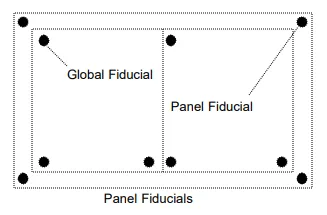
Panel fiducials, also known as global fiducials for arrayed boards, are precisely etched copper pads on the panel's frame or rails that serve as alignment targets for SMT equipment. These marks enable vision systems to detect the panel's position, rotation, and scale before component placement begins. For single boards, board-level fiducials suffice, but in panelized production, panel fiducials align the entire array, compensating for any distortions from fabrication or handling. Their importance escalates with fine-pitch components, where tolerances drop to 50 microns or less, making panel fiducial techniques essential for consistent yields.
Without proper fiducials, SMT assembly challenges like offset placement multiply across the panel, amplifying errors in BGA placement and QFP assembly. Machines use these marks to perform theta correction, adjusting for angular deviations up to several degrees. Industry experience shows that panels lacking three asymmetrically placed fiducials often require manual intervention, slowing throughput and increasing defect rates. For electrical engineers, mastering these techniques means bridging design intent with manufacturing reality, ensuring first-pass success in complex assemblies.
Technical Principles Behind Panel Fiducials
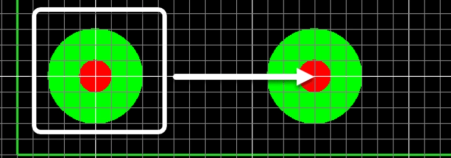
Fiducials operate on optical recognition principles, where high-contrast circular pads, typically 1 mm in diameter, allow cameras to compute exact coordinates via edge detection algorithms. Global panel fiducials form a reference triangle, with the machine triangulating position from at least three points spaced far apart, ideally near opposite corners. This setup corrects for translation in X and Y axes, as well as rotation, using the formula for affine transformations derived from the fiducial centroids. For panels larger than 200 mm, additional fiducials may be needed to account for non-linear distortions like warpage.
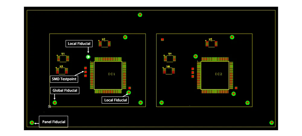
In fine-pitch assembly, local fiducials supplement panel ones, placed diagonally adjacent to components like BGAs or QFPs within 5 mm of the footprint. These local marks refine placement accuracy to under 25 microns, critical for matching tiny solder balls or leads. The IPC-7351 standard outlines requirements for fiducial integration into land patterns, emphasizing solder mask relief over the pad to maintain contrast post-fabrication. Engineers must consider illumination angles, as shiny copper reflects light, potentially causing detection failures in overhead vision systems.
Material properties also influence performance; fiducials etched from the top copper layer ensure planarity, avoiding height variations that plague filled vias or plated features. During reflow, thermal expansion minimally affects these isolated pads if surrounded by clearance zones free of traces. Vision systems calibrate against fiducial brightness thresholds, so consistent plating thickness across the panel prevents variability. Understanding these principles allows engineers to predict and mitigate alignment drifts in high-mix production runs.
Advanced Panel Fiducial Techniques for Precision
Advanced techniques extend beyond basic circles to asymmetric patterns, where fiducials incorporate deliberate shape variations like filled segments or offset holes for unambiguous orientation detection. For panels prone to warpage, common in thin flex-rigid boards, dual-layer fiducials on top and bottom enable 3D vision systems to measure Z-axis deviations and compensate dynamically. This approach addresses SMT assembly challenges in fine-pitch components by feeding warp data into placement algorithms, reducing standoff errors in BGA placement.
Hybrid fiducial arrays combine global panel marks with segmented locals, dividing large panels into zones each with its own reference trio. In QFP assembly, where lead coplanarity varies, zone-specific correction minimizes cumulative errors propagating from panel edges inward. Engineers can implement fiducial grids at 100 mm intervals for oversized panels, allowing iterative alignment passes before fine-pitch placement. Software in modern pick-and-place tools interpolates between fiducials, modeling panel bow as a polynomial surface for sub-10 micron accuracy.
Another technique involves fiducial redundancy, placing four marks in a non-rectangular trapezoid to enable outlier rejection if one is obscured by debris. For high-speed lines handling 0.4 mm pitch QFPs, laser-etched fiducials with matte finishes reduce specular reflections, improving detection under varying lighting. These methods, grounded in IPC-7351 guidelines for surface mount design, elevate panel fiducial techniques from passive references to active precision enhancers.
Best Practices for Panel Fiducial Implementation
Start with placement: position three global fiducials at least 50 mm from panel edges on tooling rails, forming an isosceles triangle with the longest side spanning 80% of the panel length. Maintain a 5 mm exclusion zone around each fiducial, free of silkscreen, vias, or components to prevent optical interference. For fine-pitch components, add two local fiducials per BGA or QFP, diagonally opposite within the footprint shadow, sized at 0.5 mm for ultra-fine pitches. Verify asymmetry by ensuring no line of reflection symmetry exists among the set.
Surface finish matters; expose bare copper without solder mask or legend overlap, and tie fiducials to ground planes for stability against vibration during transport. In double-sided panels, mirror fiducials on both layers, offset by 1 mm to aid flip detection. Panelization software should auto-generate these during array creation, but manual review confirms compliance with J-STD-001 assembly requirements. Test panels with fiducial simulators in design tools to predict machine performance before fabrication.
Integrate tooling holes nearby, as combined fiducial-hole pairs enhance mechanical registration. For high-reliability apps, gold-plate fiducials if oxidation risks exist in storage, though copper suffices for most runs. Document fiducial coordinates in Gerber files with apertures dedicated to marks. These practices systematically tackle SMT assembly challenges, boosting first-pass yields for fine-pitch components.
Troubleshooting SMT Assembly Challenges with Fiducials
Misalignment tops the list of issues, often from fiducials too close together, causing poor theta resolution; space them maximally and recheck panel DATUM definitions. If BGA placement shows systematic offsets, inspect for warpage exceeding 0.75% of panel diagonal, using fiducial-based mapping to flatten virtually. QFP assembly failures like bridging stem from local fiducial absence, leading to 50 micron drifts; retrofit designs always include them near lead rows.
Detection failures arise from contamination or mask bleed; enforce strict fab specs for clean etches and post-plate inspections. In multi-panel runs, inconsistent fiducial sizing across suppliers amplifies errors, so standardize at 1 mm diameter per IPC guidelines. Vision logs reveal root causes: low contrast signals repeat faults, fixable by increasing pad-to-clearance ratios. For chronic issues, perform DOE with fiducial variants, correlating placement CPK to mark geometry.
Panel separation stress warps rails, shifting fiducials; opt for robust V-scoring over tabs near marks. Double-sided flips demand identical fiducials; mismatches cause side-two offsets in mixed assemblies. Log machine down-times tied to fiducials, then iterate designs. These troubleshooting steps turn panel fiducial techniques into reliable safeguards against fine-pitch pitfalls.
Conclusion
Advanced panel fiducial techniques form the backbone of successful fine-pitch component assembly, directly addressing SMT assembly challenges through precise global and local alignment. Electrical engineers benefit from triangular placements, exclusion zones, and hybrid arrays that ensure accurate BGA placement and QFP assembly even on warped panels. Adhering to standards like IPC-7351 delivers consistent results, minimizing defects and maximizing throughput. Prioritize these practices in design reviews to future-proof assemblies for denser, faster production lines.
FAQs
Q1: What are the key differences between panel fiducials and local fiducials in fine-pitch components assembly?
A1: Panel fiducials align the entire array on rails for global reference, using three marks in corners to correct position and rotation. Local fiducials, placed near BGAs or QFPs, provide micron-level precision for individual component placement. Together, they overcome SMT assembly challenges by layering coarse-to-fine corrections. Best results come from 1 mm global and 0.5 mm local sizes with full clearances.
Q2: How do panel fiducial techniques improve BGA placement accuracy?
A2: Panel fiducials enable vision systems to map distortions across the array, feeding data for dynamic adjustments during BGA placement. Asymmetric patterns prevent flip errors, while redundancy handles debris. This reduces offsets below 25 microns, critical for 0.4 mm pitches. Troubleshoot by checking fiducial contrast and panel flatness for optimal yields.
Q3: What common SMT assembly challenges do poor panel fiducials cause in QFP assembly?
A3: Inadequate fiducials lead to rotational errors, causing lead misalignment and bridging in QFP assembly. Close spacing amplifies warpage effects, dropping placement CPK. Solutions include maximal spacing and exclusion zones. Per industry guidelines, three non-symmetric marks per panel resolve most issues without hardware changes.
Q4: Why is fiducial clearance important for fine-pitch components?
A4: A 5 mm clearance around fiducials prevents optical confusion from nearby traces or silkscreen, ensuring reliable detection. This zone maintains contrast for vision algorithms, vital in high-speed SMT lines with fine-pitch components. Violations cause false reads, inflating defects. Always verify in panelization to avoid assembly halts.
References
IPC-7351D — Generic Requirements for Surface Mount Design and Land Pattern Standard. IPC, 2014
J-STD-001G — Requirements for Soldered Electrical and Electronic Assemblies. IPC, 2011
IPC-6012DS — Qualification and Performance Specification for Rigid Printed Boards. IPC, 2015


