ALLPCB


If you're an electrical engineer working on surface mount technology (SMT) assembly, achieving high precision in stencil printing is critical to ensuring the quality and reliability of your printed circuit boards (PCBs). But how do you master stencil printing techniques to get consistent results? The answer lies in understanding the nuances of stencil design, solder paste application, and process control. In this comprehensive guide, we'll dive deep into the world of high precision stencil printing, exploring fine pitch stencil printing, SMT assembly precision, solder paste volume control, and stencil printing accuracy to help you optimize your manufacturing process.
Why High Precision Stencil Printing Matters in SMT Assembly
In SMT assembly, stencil printing is the first and arguably most critical step. It involves depositing solder paste onto the PCB to create the connections between components and the board. If the solder paste isn't applied with precision, you risk issues like insufficient solder, bridging, or misalignment, which can lead to defective assemblies and costly rework. High precision stencil printing ensures that the right amount of solder paste is placed exactly where it's needed, especially for fine pitch components with tight tolerances (e.g., 0.4mm or smaller pitch sizes).
For electrical engineers, the stakes are high. A single defect in a high-density PCB can cause signal integrity issues or complete failure in applications like automotive electronics or medical devices. By mastering stencil printing accuracy, you can reduce defect rates—often targeting below 50 parts per million (PPM)—and improve overall yield. Let’s explore how to achieve this level of precision.
Key Factors in Achieving SMT Assembly Precision Through Stencil Printing
To achieve high precision in SMT assembly, you need to focus on several interconnected factors during stencil printing. Let’s break them down into actionable insights.
1. Stencil Design: The Foundation of Precision
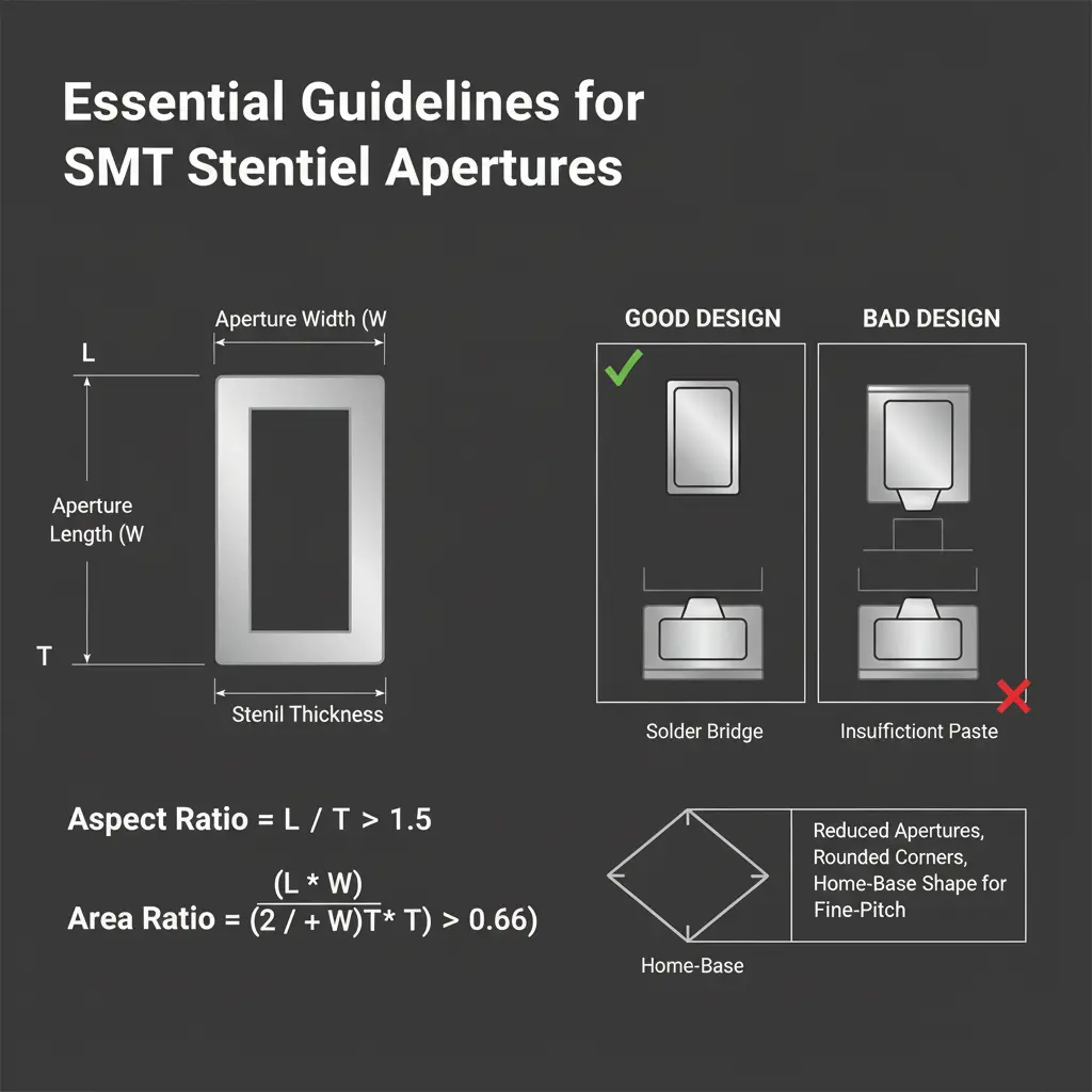
The design of your stencil directly impacts stencil printing accuracy. Stencils are typically made from stainless steel or nickel, with apertures (openings) cut to match the PCB's pad layout. For fine pitch stencil printing, where components have lead spacings as small as 0.3mm, aperture size and shape are critical.
- Aperture Size and Ratio: The area ratio (aperture opening area divided by the wall area) should ideally be above 0.66 to ensure good solder paste release. For fine pitch components, a ratio closer to 0.8 may be needed to prevent clogging.
- Trapezoidal Apertures: Laser-cut stencils with trapezoidal apertures (wider at the bottom) improve paste release by reducing adhesion to the stencil walls. This is especially important for pitches below 0.5mm.
- Stencil Thickness: Thinner stencils (e.g., 0.1mm or 100 microns) are often used for fine pitch applications to control solder paste volume. However, they must be durable enough to withstand repeated use without warping.
Pro Tip: Work closely with your stencil manufacturer to simulate paste release behavior using software tools before finalizing the design. This can save hours of trial and error on the production line.
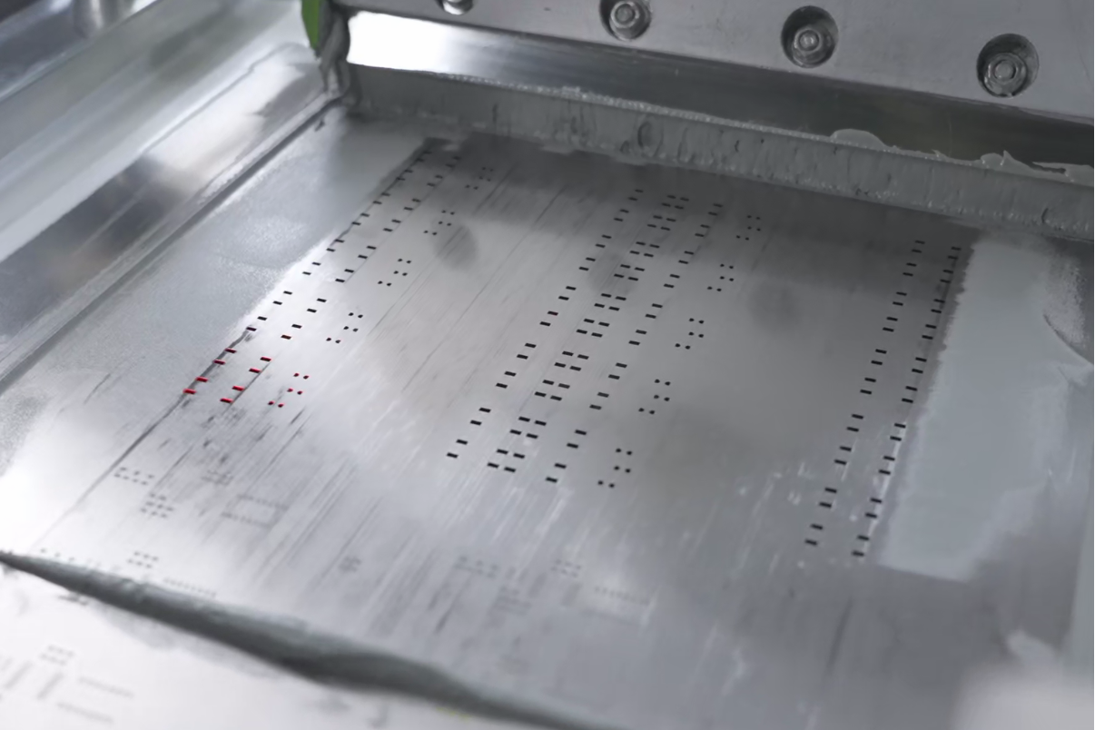
2. Solder Paste Volume Control: Getting the Right Amount Every Time
Controlling solder paste volume is a cornerstone of high precision stencil printing. Too much paste can cause bridging between pads, while too little can lead to weak joints. The goal is to deposit a consistent volume—typically within ±10% of the target—across all pads.
- Paste Selection: Choose a solder paste with the right particle size for your application. For fine pitch components, Type 4 or Type 5 pastes (particle sizes of 20-38 microns or 15-25 microns) are ideal as they flow better through small apertures.
- Print Pressure and Speed: Adjust the squeegee pressure (often between 0.2-0.5 kg/cm) and speed (20-50 mm/s) to match the stencil design and paste viscosity. Excessive pressure can cause paste to bleed under the stencil, while slow speeds may lead to incomplete filling.
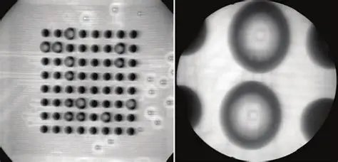
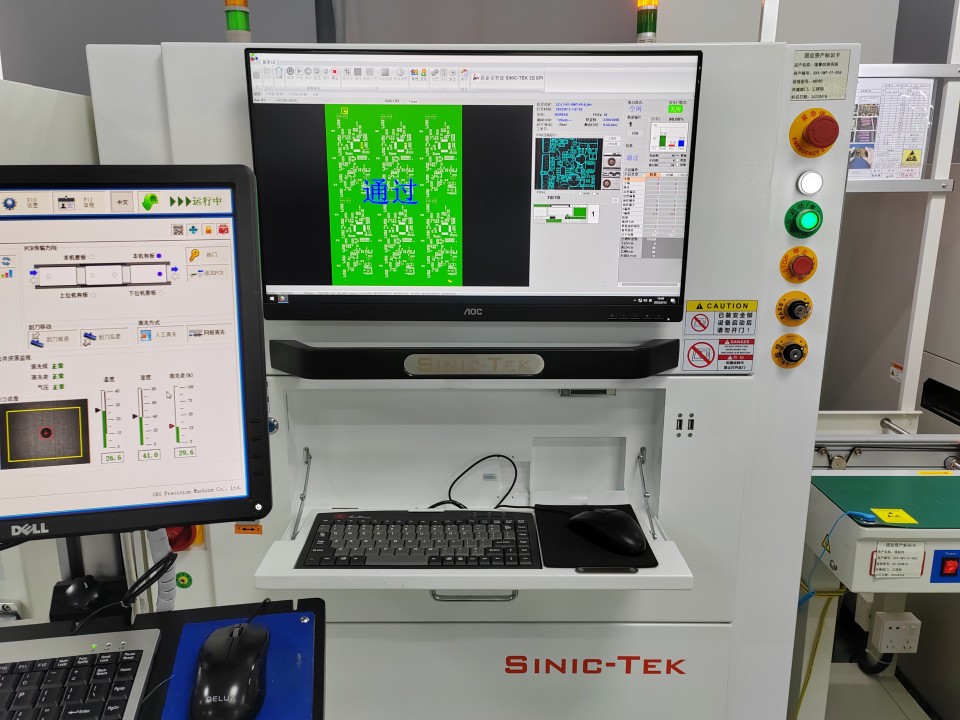
- Inspection Tools: Use 3D solder paste inspection (SPI) systems to measure paste height and volume after printing. Modern SPI machines can detect variations as small as 1 micron, allowing for real-time adjustments.
3. Fine Pitch Stencil Printing: Tackling the Challenges of Miniaturization
As electronics continue to shrink, fine pitch stencil printing has become a necessity. Components like 0201 capacitors or QFN packages with 0.4mm pitch require extreme accuracy to avoid defects. Here are some best practices:
- Electroformed Stencils: Consider using electroformed nickel stencils for ultra-fine pitch applications. These stencils offer smoother aperture walls and better wear resistance compared to traditional stainless steel, ensuring consistent results over thousands of prints.
- Alignment Precision: Misalignment by even 0.05mm can cause defects in fine pitch printing. Use vision systems on your stencil printer to align the stencil with the PCB within ±10 microns.
- Environmental Control: Maintain a cleanroom environment (Class 100,000 or better) to prevent dust or debris from clogging tiny apertures. Temperature (20-25°C) and humidity (40-60%) also affect paste behavior, so keep them stable.
Case Study: A leading automotive electronics manufacturer reduced their fine pitch defect rate from 200 PPM to under 30 PPM by switching to electroformed stencils and implementing automated alignment systems. This not only improved reliability but also cut rework costs by 40%.
4. Stencil Printing Accuracy: Process Control and Maintenance
Even the best stencil design won’t deliver results if the printing process isn’t tightly controlled. Stencil printing accuracy depends on consistent machine setup and regular maintenance.
- Printer Calibration: Calibrate your stencil printer weekly to ensure squeegee pressure and alignment remain within specs. A misaligned squeegee can skew paste deposits by up to 0.1mm, enough to cause defects on fine pitch boards.
- Stencil Cleaning: Clean the stencil underside after every 5-10 prints to remove residual paste. Automated under-stencil cleaning systems with solvent wipes can achieve this without stopping production.
- Wear Monitoring: Monitor stencil wear, especially for high-volume runs. After 50,000 prints, aperture edges may degrade, reducing accuracy. Replace stencils before defects spike.
Common Challenges in High Precision Stencil Printing and How to Overcome Them
Even with the best practices in place, challenges can arise during stencil printing. Here are some common issues electrical engineers face and how to address them:
1. Solder Paste Bridging
Bridging occurs when excess paste connects adjacent pads, often due to overpressure or poor stencil design. To prevent this, reduce squeegee pressure by 10-20% and ensure the stencil’s area ratio is optimized. Post-print SPI can catch bridging early, allowing for immediate correction.
2. Insufficient Solder Paste
If pads receive too little paste, joints may fail under thermal stress. This often happens with clogged apertures or low area ratios. Increase stencil thickness by 0.02mm or switch to a finer paste type. Regular cleaning also helps.
3. Misalignment Issues
Misalignment between the stencil and PCB can ruin an entire batch. Invest in printers with high-resolution vision systems (accuracy of ±5 microns) and double-check fiducial mark placement on your PCB design.
Advanced Techniques for SMT Assembly Precision
For engineers pushing the boundaries of SMT assembly precision, consider these advanced strategies:
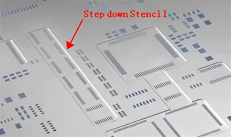
- Step Stencils: Use step stencils with varying thicknesses in different areas to control paste volume for mixed-component boards. For example, a 0.15mm thickness for standard components and 0.1mm for fine pitch areas.
- Nano-Coatings: Apply nano-coatings to stencil surfaces to reduce paste adhesion and improve release, especially for ultra-fine apertures. This can extend stencil life by up to 20%.
- Closed-Loop Feedback: Integrate SPI data with your stencil printer for real-time adjustments. If paste volume deviates by more than 5%, the printer can automatically tweak pressure or speed.
Tools and Equipment for High Precision Stencil Printing
Investing in the right tools can make a significant difference in achieving stencil printing accuracy. Here’s what to prioritize:
- Automatic SMT Stencil Printers: Look for printers with vision alignment systems and programmable parameters. Models like the DEK Horizon or MPM Momentum offer precision within ±12.5 microns.
- 3D SPI Machines: Systems like the Koh Young Zenith or CyberOptics SE600 provide detailed paste volume analysis, helping you maintain consistency.
- Stencil Inspection Tools: Use laser-based tools to check aperture dimensions after manufacturing and during use to detect wear early.
Conclusion: Elevating Your SMT Assembly with Precision Stencil Printing
Achieving high precision in SMT assembly starts with mastering stencil printing techniques. By focusing on stencil design, solder paste volume control, fine pitch stencil printing, and process accuracy, you can significantly reduce defects and improve the reliability of your PCBs. Whether you're dealing with fine pitch components or high-density designs, the actionable tips and advanced strategies in this guide—such as optimizing area ratios, using electroformed stencils, and integrating SPI feedback—can help you stay ahead in electronics manufacturing.