 ALLPCB


Introduction
Aerospace electronics operate under conditions that push the limits of material science and engineering precision. Printed circuit boards (PCBs) in aircraft, satellites, and missiles face extreme temperatures, rapid pressure changes, high vibrations, and exposure to radiation or vacuum. Any contamination left on these boards can lead to catastrophic failures, compromising mission success and safety. Aerospace electronics cleaning refers to specialized processes that remove residues, particulates, and ionic contaminants to achieve the ultra-high cleanliness required for long-term reliability. This article explores the principles, methods, and best practices for cleaning for high-reliability PCBs in such demanding applications. By adhering to established standards, engineers can mitigate risks and ensure performance in extreme environments.
Why Aerospace Electronics Cleaning Matters
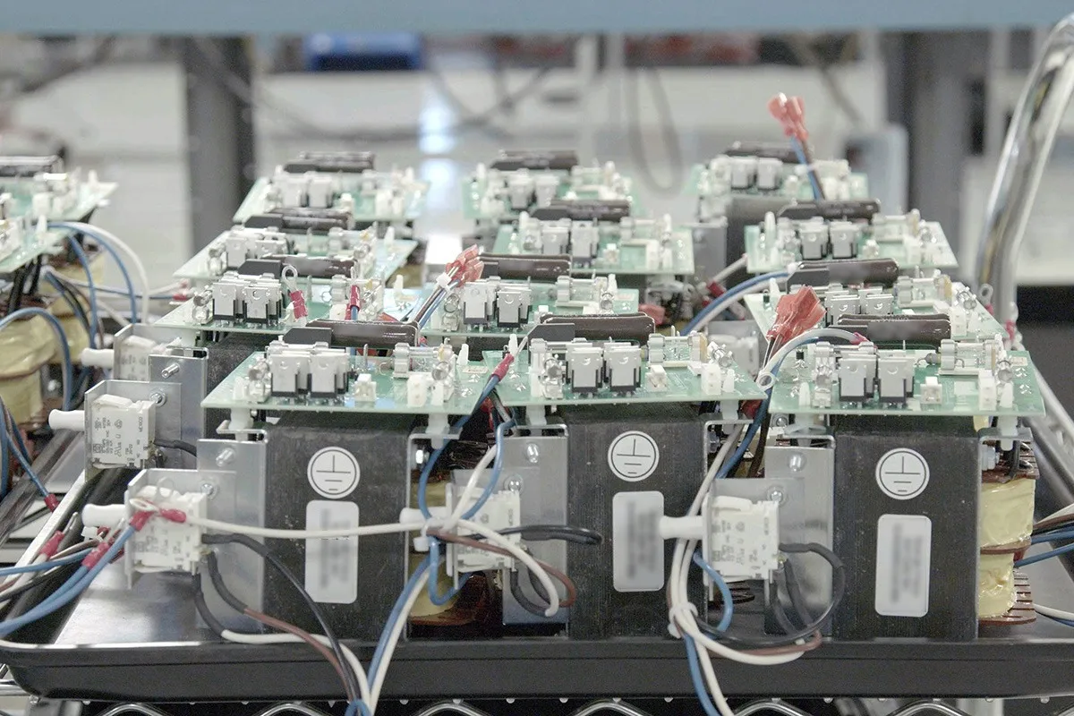
In aerospace systems, PCBs serve as the backbone for avionics, navigation, and control functions. Flux residues from soldering, handling particulates, and fabrication oils can remain even after initial processing. These contaminants become problematic when exposed to temperature cycling from -55°C to over 125°C, humidity fluctuations, or altitude-induced condensation. Ionic residues promote electrochemical migration, where metal dendrites grow between conductors, causing shorts. Particulates can dislodge under vibration, leading to intermittent contacts or abrasion. Cleaning for high-reliability PCBs prevents these issues, extending mean time between failures (MTBF) and meeting aerospace PCB standards.
Factory-driven insights reveal that unclean boards often fail accelerated life testing, simulating years of service in months. Without proper cleaning, corrosion accelerates in the presence of moisture, even in sealed enclosures. Standards like IPC Class 3 define the workmanship level for such applications, emphasizing contamination control. Engineers must prioritize cleaning to align with qualification requirements for flight hardware. Ultimately, thorough cleaning translates to fewer field returns and higher system confidence.
Challenges of Extreme Environment Cleaning
Extreme environments amplify the impact of even microscopic contaminants on PCBs. In space, vacuum conditions cause outgassing from residues, potentially contaminating optical surfaces or sensors. High-altitude aircraft encounter thermal shock and low pressure, drawing moisture into board assemblies. Vibrations exceeding 20g RMS can mobilize particles, bridging fine-pitch traces spaced under 0.1 mm. Radiation hardens some polymers while softening fluxes, altering their chemical stability. These factors demand cleaning processes that achieve residue levels below detectable limits without introducing new defects.
Water-based cleaning poses risks in high-reliability scenarios due to incomplete drying, leading to hydration of salts. Solvent compatibility with aerospace materials like polyimides and ceramics is critical to avoid swelling or delamination. No-clean fluxes, while convenient, often leave higher ionic content unsuitable for uninsulated environments. Balancing thoroughness with material preservation requires process validation. Factory experience shows that mismatched cleaning can increase bow and twist, complicating assembly.
Technical Principles of Aerospace PCB Cleaning
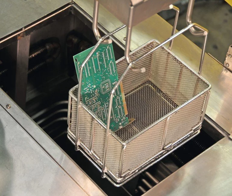
Cleaning relies on physical, chemical, and sometimes plasma mechanisms to dislodge and solubilize contaminants. Vapor degreasing uses solvent vapors to condense on surfaces, dissolving fluxes and oils through repeated evaporation-condensation cycles. This method excels for complex geometries, penetrating under components without mechanical stress. Ultrasonic cleaning employs cavitation bubbles generated by high-frequency sound waves, imploding to shear particulates from traces and vias. Precision control of frequency and power prevents damage to fine features.
Plasma cleaning, a dry process, uses ionized gases to etch organic residues via reactive species. It leaves no liquid residue, ideal for moisture-sensitive devices. Chemical principles involve selecting solvents with high Kb values for flux activation energy, ensuring rapid dissolution without attacking base materials. Surface tension and wetting agents enhance coverage on hydrophobic surfaces. Rinse steps must match solvent polarity to avoid re-deposition. These principles ensure cleanliness verifiable by resistivity of solvent extract (ROSE) testing.
Best Practices for Cleaning High-Reliability PCBs
Start with process selection based on contaminant type: rosin fluxes need alcohol or hydrocarbon solvents, while water-soluble require deionized rinses. Implement inline cleaning immediately post-soldering to prevent baked-on residues. Use filtered, recirculated fluids to maintain consistency and reduce waste. Drying must achieve zero water content, often via hot air or vacuum ovens, preventing hydrolysis. Bake-out steps post-cleaning volatilize trapped volatiles.
Adhere to IPC-CH-65 guidelines for cleaning printed boards and assemblies, which outline process controls and verification. For space applications, IPC-6012DS specifies performance for rigid boards in military avionics, including contamination limits. Segregate cleaning zones in cleanrooms meeting ISO 14644 Class 5 or better. Validate with ion chromatography for specific ions like chlorides below parts-per-billion levels. Document all parameters for traceability.
Factory protocols include multi-stage rinsing with conductivity monitoring under 1 microsiemens per centimeter. Avoid aggressive agitation on gold-plated contacts to prevent wear. For assembled boards, mask sensitive areas before immersion. Post-clean inspection under 10x magnification confirms no white residue or haze. These practices align with J-STD-001 requirements for soldered assemblies, ensuring high-reliability outcomes.
Verification and Testing Methods
Post-clean verification confirms effectiveness through multiple orthogonal tests. Visual inspection per IPC-A-610 criteria detects particulates larger than 50 microns. ROSE testing extracts ions into solvent, measuring resistivity; values above 100 megaohm-cm indicate success for many applications. Ion chromatography quantifies specific anions and cations, providing detailed profiles.
Surface insulation resistance (SIR) testing simulates field conditions with bias voltage across comb patterns. Under humidity and temperature, SIR drop signals migration risk. Particle counting via laser scanning or microscopy ensures low counts on critical surfaces. X-ray fluorescence checks for heavy metals. Combine these for comprehensive assurance.
Troubleshooting Common Cleaning Issues
Residues persisting after cleaning often stem from incompatible fluxes or insufficient contact time. Increase immersion duration or temperature, but monitor for material limits. Uneven cleaning on dense boards suggests shadowing; optimize basket orientation or use agitation. Water spots indicate poor drying; extend bake times or use IPA vapor. Dendrite precursors show in SIR fails; switch to lower-halide fluxes.
Factory troubleshooting involves root cause analysis via microscopy and FTIR spectroscopy. Adjust pH for aqueous processes to neutralize residues fully. Reclean suspect lots only after confirming process drift. These steps restore compliance without yield loss.
Conclusion
Aerospace electronics cleaning is non-negotiable for reliability in extreme environments. By mastering methods like vapor degreasing and ultrasonic, and verifying with ROSE and SIR, engineers achieve contamination-free PCBs. Standards such as IPC-CH-65, IPC-6012DS, and J-STD-001 provide the framework for consistency. Factory insights underscore proactive process control over reactive fixes. Implementing these ensures PCBs withstand thermal shocks, vibrations, and vacuums, safeguarding missions. Prioritize cleaning to elevate aerospace system performance.
FAQs
Q1: What are the main contaminants targeted in aerospace electronics cleaning?
A1: Aerospace electronics cleaning focuses on flux residues, particulates, and ionic salts from soldering and handling. These cause electrochemical migration and corrosion in extreme environments with high vibration and temperature cycles. Cleaning for high-reliability PCBs uses solvents, vapor degreasing, or ultrasonics to remove them thoroughly. Verification via ROSE testing confirms low ion levels, aligning with aerospace PCB standards for long-term reliability.
Q2: Why is vapor degreasing preferred for extreme environment cleaning?
A2: Vapor degreasing excels due to its ability to penetrate tight spaces and evaporate cleanly, leaving no residue. It handles complex aerospace PCBs without mechanical damage, which is crucial under vibration. With proper solvent selection, it is compatible with polyimides and other aerospace materials and aligns with IPC-CH-65 guidance. Drying is inherent, reducing moisture risks in altitude applications and improving MTBF in harsh conditions.
Q3: How do aerospace PCB standards influence cleaning processes?
A3: Standards such as IPC-6012DS and J-STD-001 mandate stringent cleanliness and process controls for space and avionics boards. They define limits on ionic contamination to prevent failures during thermal cycling and in vacuum. Cleaning processes must validate compliance through SIR, ROSE, and ion chromatography. Factory adherence ensures qualification for flight hardware and drives selection of no-residue methods for high-reliability PCBs.
Q4: What testing verifies effective cleaning for high-reliability PCBs?
A4: Common verification includes ROSE for total ionic content, SIR under bias, humidity, and temperature, and visual inspection per IPC-A-610. Ion chromatography identifies specific ions such as chlorides and bromides. Particle counting and, where relevant, XRF for residues provide additional assurance. Consistent passing results indicate robust, repeatable cleaning processes suitable for extreme environments.
References
IPC-CH-65 — Guidelines for Cleaning of Printed Boards and Assemblies. IPC.
IPC-6012DS — Qualification and Performance Specification for Rigid Printed Boards in Space and Military Avionics. IPC.
J-STD-001 — Requirements for Soldered Electrical and Electronic Assemblies. IPC/JEDEC.
ISO 14644-1 — Cleanrooms and Associated Controlled Environments. ISO.


