 ALLPCB


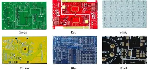
Blue solder mask has gained widespread adoption in printed circuit board design because of its distinctive appearance and utility in board identification during multi-project manufacturing runs. Engineers often select it to differentiate assemblies visually while maintaining compatibility with standard fabrication processes. At the same time, the darker tone of blue solder mask can reduce the visibility of traditional white silkscreen markings compared with lighter masks. This reduction directly affects blue solder mask silkscreen readability during component placement and final inspection. Proper contrast management therefore becomes essential for maintaining assembly accuracy and long-term board serviceability.
Why Optimal Silkscreen Contrast Matters in Blue Solder Mask Designs
Clear component marking and labeling on blue solder mask PCBs support precise orientation of parts during automated and manual assembly. Insufficient contrast increases the risk of misplacement or reversed polarity, particularly for small-outline components and dense layouts. In production environments, operators rely on these markings for first-article verification and rework tasks. Blue solder mask component marking that remains legible under factory lighting conditions therefore contributes to higher first-pass yields and lower defect rates. Industry practice shows that addressing contrast early in the design phase prevents costly revisions after fabrication.
Technical Principles of Contrast on Blue Solder Mask
Solder mask color influences surface reflectance and the perceived brightness of overlying silkscreen ink. Blue masks typically absorb more visible light in the shorter wavelengths, which can make white or light-colored legends appear less distinct unless the ink formulation provides high opacity. Silkscreen application involves screen printing or direct imaging of epoxy-based or UV-curable inks, followed by curing that must not alter the underlying mask adhesion. Factors such as ink thickness, particle size distribution, and surface texture of the cured mask all interact to determine final contrast. Engineers evaluate these interactions through visual inspection protocols that consider both ambient and directional lighting conditions typical of assembly lines.
Practical Solutions and Best Practices for Improved Readability
Design teams achieve reliable blue solder mask labeling by specifying high-opacity white silkscreen ink and verifying minimum line widths suitable for the chosen fabrication process. Increasing ink deposit thickness within acceptable limits enhances coverage without compromising fine-feature resolution. Some fabricators apply a light surface texturing or matte finish to the blue mask to reduce specular reflection and improve diffuse contrast. During layout, designers position critical reference designators away from high-density routing areas where shadow effects might further reduce visibility. Pre-production samples undergo lighting tests that simulate both inspection stations and automated optical inspection equipment to confirm acceptable contrast before volume production.
Process controls during assembly further support blue solder mask assembly success. Stencil and placement programs incorporate fiducial recognition that does not depend solely on silkscreen contrast, yet human-readable markings remain important for manual verification steps. Post-assembly cleaning must avoid aggressive solvents that could degrade silkscreen adhesion or alter its color. When contrast issues appear after initial builds, engineers review ink batch records and mask gloss levels rather than assuming design changes are required.

Troubleshooting Common Contrast Issues
When markings appear washed out, the first step is to confirm that the silkscreen ink meets the specified opacity rating for the chosen blue mask shade. Variations in mask color saturation between lots can shift the required ink properties. Adjusting the silkscreen artwork to use slightly thicker strokes or adding a second print pass in critical areas often restores readability without redesign. In cases where environmental lighting differs significantly from the factory standard, supplemental labels or laser-etched alternatives may supplement silkscreen on selected boards. Consistent documentation of these adjustments helps maintain process repeatability across multiple production runs.
Conclusion
Blue solder mask PCBs offer aesthetic and identification advantages, yet they require deliberate attention to silkscreen contrast to support efficient assembly and inspection. By understanding reflectance interactions, specifying appropriate ink properties, and validating designs under realistic conditions, engineers maintain clear component marking and labeling. These steps align with established quality expectations and contribute to reliable manufacturing outcomes.
FAQs
Q1: How does blue solder mask affect silkscreen readability compared with green masks?
A1: Blue solder mask tends to absorb more light in certain wavelengths, which can lower the apparent brightness of white silkscreen unless higher-opacity inks or adjusted thicknesses are used. This difference becomes noticeable during blue solder mask silkscreen readability checks under standard factory lighting. Engineers address it through material selection and pre-production verification rather than post-fabrication fixes.
Q2: What steps improve blue solder mask component marking during assembly?
A2: Specifying high-opacity white ink, verifying minimum feature sizes, and confirming contrast on sample boards before volume runs help maintain clear markings. Additional process controls such as lighting consistency and gentle cleaning further protect blue solder mask component marking integrity throughout assembly.
Q3: Can silkscreen color choices other than white work on blue solder mask?
A3: Yellow or certain high-contrast formulations sometimes provide acceptable visibility, yet white remains the most common choice because of its broad compatibility and established performance. Any alternative requires testing to ensure it meets the same readability standards as white ink on blue solder mask.
Q4: How do industry standards guide silkscreen quality on colored solder masks?
A4: Standards such as IPC-A-600K define visual acceptability criteria that apply regardless of mask color, including requirements for legibility of markings. IPC-6012E further addresses qualification aspects relevant to overall board performance, including surface finishes that influence contrast.
References
IPC-A-600K — Acceptability of Printed Boards. IPC, 2020
IPC-6012E — Qualification and Performance Specification for Rigid Printed Boards. IPC, 2017
JEDEC J-STD-020E — Moisture/Reflow Sensitivity Classification. JEDEC, 2014


