 ALLPCB


Why Solder Mask Thickness Matters in Automotive Applications
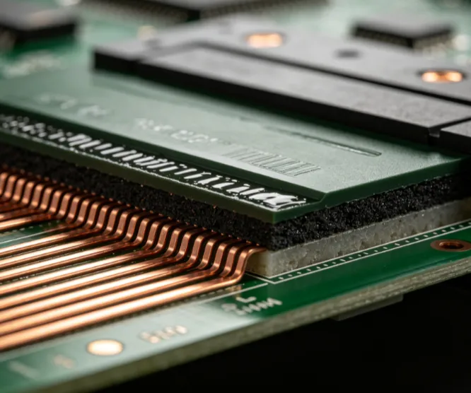
Solder mask functions as both an electrical insulator and a barrier against environmental contaminants on automotive PCBs. In vehicles, boards experience wide temperature swings from subzero cold starts to engine compartment heat, combined with mechanical stress from road conditions. Insufficient or excessive thickness can lead to inadequate trace coverage, trapped moisture, or increased stress during thermal expansion. These factors directly affect the ability of high-reliability PCBs to maintain functionality over the vehicle service life. Industry standards guide the selection process to balance protection with process capability in high-volume manufacturing.
Technical Principles of Solder Mask Thickness Control
Solder mask thickness influences several interrelated mechanisms that determine board performance. The coating must fully encapsulate copper features to prevent oxidation and electrochemical migration while allowing proper solder wetting during assembly. Variations in thickness affect adhesion strength to the substrate and can contribute to localized stress concentrations that promote cracking under vibration. Thermal expansion mismatch between the mask material and underlying layers becomes more pronounced with improper thickness, potentially leading to warpage or delamination during temperature cycling. Controlled thickness also supports consistent dielectric properties that help maintain signal integrity in dense automotive electronic modules.
Mechanisms in Harsh Environments
Automotive PCBs encounter combined stressors that amplify the importance of uniform solder mask thickness. Moisture absorption through thin or porous mask areas can initiate corrosion at copper interfaces, while overly thick deposits may trap volatiles that expand during reflow or high-temperature operation. Vibration induces cyclic mechanical loading where thickness inconsistencies create stress risers at trace edges. Chemical exposure from road salts or fluids further tests the barrier properties, making consistent thickness essential for maintaining insulation resistance over time. These mechanisms explain why automotive designs place emphasis on thickness verification as part of overall quality protocols.
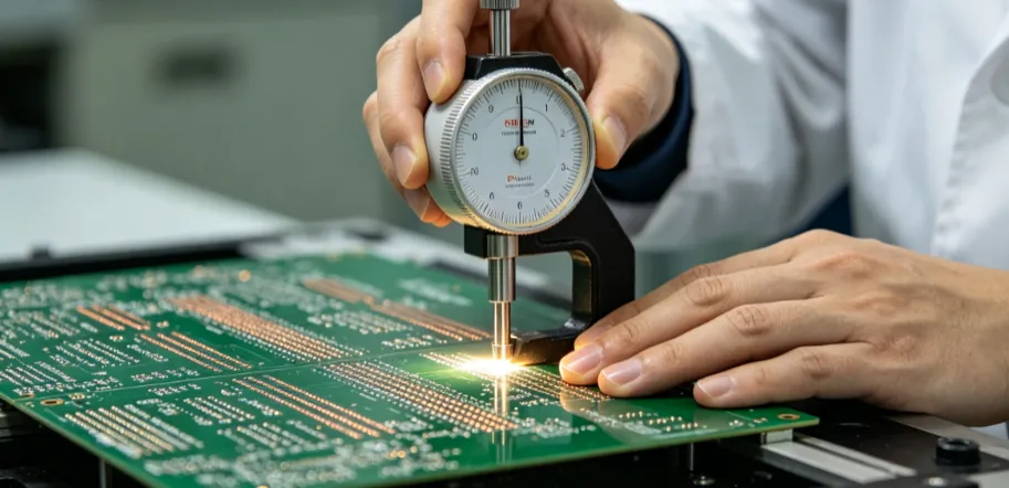
Best Practices for Specifying and Verifying Thickness
Design teams establish thickness requirements early in the layout phase by referencing applicable performance specifications for rigid boards. Collaboration between design and manufacturing engineers ensures that selected values align with available process capabilities and inspection methods. Verification typically involves cross-sectional analysis or non-destructive measurement techniques at multiple board locations to confirm uniformity. Process controls during application, such as screen printing parameters or liquid photoimageable coating adjustments, help achieve repeatable results. Documentation of thickness data supports traceability required for automotive supply chains.
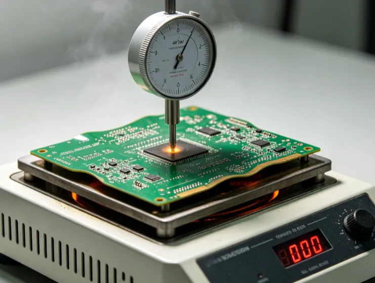
Quality Control and Testing Approaches
Quality control procedures incorporate thickness checks as part of incoming material and finished board inspection. Acceptance criteria derive from industry standards that define minimum coverage and maximum build-up limits to avoid functional issues. Thermal shock and humidity testing further validate that the chosen thickness maintains integrity under accelerated life conditions representative of automotive use. Non-conformances in thickness often trigger root-cause analysis focused on coating application variables or substrate preparation. Consistent application of these practices reduces the risk of field returns in safety-critical systems.
Conclusion
Solder mask thickness represents a foundational element in achieving the reliability demanded by automotive PCB applications. Through careful specification aligned with established standards, engineers can address the combined challenges of thermal, mechanical, and chemical stresses encountered in vehicle environments. Structured design reviews, process controls, and verification steps ensure that this parameter contributes positively to overall board performance. Attention to these details supports the development of high-reliability PCBs that meet the expectations of automotive qualification programs.
FAQs
Q1: What role does solder mask thickness play in automotive PCB reliability?
A1: Solder mask thickness directly affects the protective barrier over copper features in automotive PCBs, influencing resistance to moisture, chemicals, and thermal cycling common in vehicle environments. Proper thickness supports insulation integrity and helps prevent corrosion or delamination that could compromise high-reliability PCB performance. Design choices in this area align with overall efforts to meet stringent automotive requirements.
Q2: How do industry standards guide solder mask thickness for automotive applications?
A2: Standards such as those from IPC provide qualification and acceptability criteria that inform thickness specifications for rigid printed boards used in demanding conditions. These guidelines help ensure adequate coverage while maintaining manufacturability and electrical performance. Compliance supports the broader goals of high-reliability PCB designs intended for harsh environments.
Q3: Why is uniform solder mask thickness important during PCB assembly?
A3: Uniform thickness promotes consistent solder wetting and prevents issues such as mask lifting or incomplete coverage that can lead to assembly defects. In automotive PCB production, this uniformity contributes to reliable interconnections under subsequent thermal and mechanical stresses. Verification steps during manufacturing help maintain these characteristics.
Q4: What considerations apply when selecting solder mask thickness for high-reliability PCBs?
A4: Selection involves balancing environmental protection needs against factors such as trace geometry, assembly processes, and thermal expansion behavior in automotive settings. Reference to relevant standards ensures the chosen thickness meets performance expectations without introducing new failure modes. Engineering reviews typically evaluate these trade-offs early in the design cycle.
References
IPC-6012E — Qualification and Performance Specification for Rigid Printed Boards. IPC, 2017
IPC-A-600K — Acceptability of Printed Boards. IPC, 2020
JEDEC J-STD-020E — Moisture/Reflow Sensitivity Classification. JEDEC, 2014


