 ALLPCB


In the fast-evolving world of automotive electronics, rigid-flex PCBs are becoming a game-changer. These hybrid circuit boards combine the stability of rigid PCBs with the adaptability of flexible circuits, making them ideal for modern vehicles packed with advanced systems. If you're looking into automotive rigid-flex PCB design or exploring flexible PCB applications for vehicles, you're in the right place. This blog dives deep into how rigid-flex PCBs are used in automotive systems like lighting and sensors, along with key design tips and best practices to ensure reliability and performance.
Whether you're an engineer working on automotive PCB assembly or a designer focusing on rigid-flex PCB reliability, this guide offers practical insights to help you navigate the challenges of designing for harsh automotive environments. Let's explore the critical considerations and strategies for success.
What Are Rigid-Flex PCBs and Why Are They Vital for Automotive Applications?
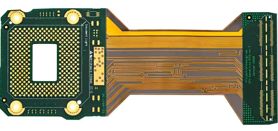
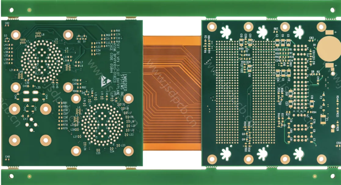
Rigid-flex PCBs are circuit boards that integrate rigid and flexible sections into a single unit. The rigid parts provide structural support for mounting components, while the flexible sections allow the board to bend and fit into tight or irregular spaces. This unique combination makes them perfect for automotive applications where space is limited, and durability is non-negotiable.
In vehicles, electronics are everywhere—from powertrains in electric cars to advanced driver-assistance systems (ADAS). Rigid-flex PCBs are often used in automotive lighting PCB designs for LED headlights and interior lighting, as well as in automotive sensor PCB setups for cameras, radar, and LiDAR systems. Their ability to reduce weight, save space, and withstand vibrations and temperature swings makes them a top choice for modern vehicle designs.
Key Benefits of Rigid-Flex PCBs in Automotive Systems
Before diving into design considerations, it's worth understanding why rigid-flex PCBs are so valuable in automotive applications. Here are some standout advantages:
- Space Efficiency: Vehicles have limited room for electronics. Rigid-flex PCBs can fold and conform to compact or irregular shapes, fitting into tight spaces like dashboards or headlight assemblies.
- Reduced Weight: By eliminating the need for multiple connectors and cables, these boards help reduce overall vehicle weight, which is critical for fuel efficiency in traditional cars and range optimization in electric vehicles.
- Enhanced Reliability: With fewer connection points, there's a lower risk of failure due to loose connectors or broken wires, boosting rigid-flex PCB reliability in harsh conditions.
- Durability: Automotive environments involve vibrations, shocks, and extreme temperatures. Rigid-flex PCBs are built to endure these challenges, ensuring long-term performance.
Design Considerations for Automotive Rigid-Flex PCBs
Designing rigid-flex PCBs for automotive use isn't a straightforward task. The harsh operating conditions and strict safety standards demand careful planning. Below are the critical factors to keep in mind during the design process for automotive rigid-flex PCB design.
1. Material Selection for Harsh Environments
The materials used in rigid-flex PCBs must withstand the extreme conditions inside a vehicle. Temperatures can range from -40°C to 85°C or higher near engines, while humidity and chemical exposure (like road salt) add further stress.
For the rigid sections, high-Tg (glass transition temperature) materials like FR4 with a Tg of 130°C or above are often used to handle heat. For flexible sections, polyimide (PI) is a common choice due to its excellent thermal stability and flexibility. Some designs may also use liquid crystalline polymer (LCP) for high-frequency applications, such as radar sensors, where signal integrity at frequencies above 1 GHz is critical.
Adhesives and prepregs (pre-impregnated materials) also matter. Opt for no-flow prepregs with a Tg of at least 105°C to ensure bonding stability under thermal stress. Choosing materials with a low coefficient of thermal expansion (CTE) helps prevent cracking or delamination during temperature cycles.
2. Bend Radius and Flexibility Planning
One of the biggest advantages of rigid-flex PCBs is their ability to bend, but this must be carefully managed. A bend radius that's too tight can cause stress on the flexible layers, leading to cracks or signal degradation. As a general rule, the bend radius should be at least 10 times the thickness of the flexible material. For a 0.1 mm thick flexible layer, aim for a minimum bend radius of 1 mm.
In automotive applications like automotive lighting PCB designs, where the board might need to wrap around a curved headlight housing, plan the flex areas early in the design phase. Avoid placing components or vias in the bend zones to prevent mechanical stress on solder joints.
3. Thermal Management for High-Heat Areas
Vehicles generate significant heat, especially in areas like the engine compartment or near high-power LED lighting systems. Poor thermal management can lead to component failure or reduced lifespan. During automotive PCB assembly, ensure that heat dissipation is addressed through proper layout and material choices.
Use thermal vias to transfer heat away from critical components to a heat sink or metal layer. For high-power applications, consider incorporating copper planes with a thickness of 2 oz or more to improve heat distribution. In designs for automotive sensor PCB systems, where precision is key, maintain a consistent operating temperature to avoid sensor drift—thermal stability can keep sensor accuracy within ±0.5% under varying conditions.
4. Signal Integrity in High-Frequency Applications
Modern vehicles rely on high-frequency signals for systems like radar and communication modules in ADAS. Rigid-flex PCBs must maintain signal integrity to prevent data loss or interference. For signals operating at 1 GHz or higher, impedance mismatches can cause significant issues. Aim for a controlled impedance of 50 ohms for single-ended signals or 100 ohms for differential pairs, with a tolerance of ±10%.
To achieve this, use proper trace widths and spacing based on the dielectric constant of the material (typically 3.5–4.5 for PI). Avoid sharp bends in high-frequency traces, as they can act as antennas and introduce noise. Ground planes beneath signal layers also help reduce electromagnetic interference (EMI), which is crucial in the crowded electronic environment of a vehicle.
5. Compliance with Automotive Standards
Automotive electronics must meet strict industry standards to ensure safety and reliability. Rigid-flex PCBs should comply with guidelines like ISO 26262 for functional safety and AEC-Q100 for component stress testing. These standards cover everything from thermal cycling endurance (1,000 cycles between -40°C and 85°C) to vibration resistance (up to 20G force).
During the design phase, simulate environmental stresses using software tools to predict failure points. Testing prototypes under real-world conditions—like temperature shocks or mechanical vibrations—can help validate rigid-flex PCB reliability before mass production.
Best Practices for Rigid-Flex PCB Design in Automotive Applications
Beyond the core design considerations, following best practices can elevate the quality and performance of rigid-flex PCBs in vehicles. These tips are tailored for engineers working on flexible PCB applications in automotive systems.
1. Optimize Component Placement
Place heavier components on the rigid sections of the PCB to avoid stressing the flexible areas. For example, in an automotive lighting PCB, position power drivers and capacitors on the rigid part, while using the flexible section to connect to the LED array. This approach minimizes mechanical strain and extends the board's lifespan.
2. Minimize Layer Count in Flex Areas
Keep the number of layers in the flexible sections as low as possible—ideally one or two layers. Additional layers increase stiffness and reduce flexibility, making the board more prone to damage during bending. For complex designs, route critical signals through the rigid areas instead.
3. Use Strain Relief Features
Incorporate strain relief designs, such as teardrop-shaped pads or curved traces, at the transition points between rigid and flex sections. This reduces stress concentration and prevents cracking. In automotive sensor PCB designs, where boards may experience constant vibration, strain relief can significantly improve durability.
4. Collaborate Early with Manufacturers
Rigid-flex PCB fabrication is complex, especially for automotive applications. Work closely with your manufacturing partner during the design stage to ensure that your layout aligns with their capabilities. Discuss stack-up options, material availability, and assembly processes to avoid costly redesigns. Early collaboration can also streamline automotive PCB assembly and reduce lead times.
5. Test for Environmental Durability
Before finalizing a design, subject prototypes to rigorous environmental testing. Simulate conditions like thermal cycling, humidity exposure (up to 85% relative humidity), and vibration (10–500 Hz range) to ensure the board performs reliably in real-world scenarios. For instance, a rigid-flex PCB for an ADAS camera should maintain functionality after 500 hours of salt spray testing to resist corrosion from road conditions.

Applications of Rigid-Flex PCBs in Automotive Systems
Rigid-flex PCBs are versatile and find use in various automotive systems. Here are two key areas where they shine:
Automotive Lighting Systems
In automotive lighting PCB designs, rigid-flex boards enable compact and efficient layouts for LED headlights, taillights, and interior lighting. Their flexibility allows them to wrap around curved or angled fixtures, while the rigid sections support power management components. This setup reduces wiring complexity and enhances the aesthetic design of modern vehicles.
Automotive Sensor Modules
For automotive sensor PCB applications, rigid-flex designs are critical in systems like radar, LiDAR, and parking cameras. These boards can fit into small sensor housings while maintaining signal integrity for high-frequency data. Their durability ensures consistent performance, even under the vibrations and temperature swings of daily driving.
Challenges in Automotive Rigid-Flex PCB Design
While rigid-flex PCBs offer many benefits, they come with challenges that designers must address:
- High Initial Costs: The materials and manufacturing processes for rigid-flex PCBs are more expensive than traditional rigid boards. However, the long-term savings from reduced connectors and improved reliability often offset this.
- Complex Design Process: Balancing flexibility and rigidity requires precise planning and simulation to avoid mechanical or electrical failures.
- Limited Repairability: Once assembled, rigid-flex PCBs are harder to repair compared to standard boards, making thorough testing essential before deployment.
Conclusion: Building Reliable Rigid-Flex PCBs for the Future of Automotive Electronics
Rigid-flex PCBs are transforming the automotive industry by enabling compact, durable, and high-performing electronic systems. From automotive lighting PCB designs to automotive sensor PCB modules, their unique blend of rigidity and flexibility meets the demands of modern vehicles. By focusing on material selection, thermal management, signal integrity, and compliance with industry standards, designers can ensure rigid-flex PCB reliability in even the harshest conditions.
Whether you're tackling automotive rigid-flex PCB design or optimizing flexible PCB applications, the best practices outlined here—such as optimizing component placement and testing for durability—can guide you toward success. As vehicles continue to integrate more electronics, mastering rigid-flex PCB design will be key to staying ahead in this dynamic field.
With the right approach and attention to detail, you can create automotive electronics that are not only innovative but also built to last. Let's keep pushing the boundaries of what's possible on the road.


