ALLPCB


Market overview of mobile RF systems
The mobile radio frequency (RF) unit handles transmit and receive functions for handset RF signals (see Figure 1). It mainly includes transceiver units, power amplification, switching, and antenna modules. RF receive circuits perform filtering, amplification, and demodulation; RF transmit circuits handle baseband modulation, frequency conversion, and power amplification. RF components are widely used in 5G technologies, and components such as antennas, filters, power amplifiers, and switches are expected to see rapid growth. The global RF market is currently dominated by five major vendors: Skyworks, Qualcomm, Qorvo, Broadcom, and Murata. Driven by 5G, the mobile RF market size is expected to grow substantially, with forecasts indicating market expansion through 2023.
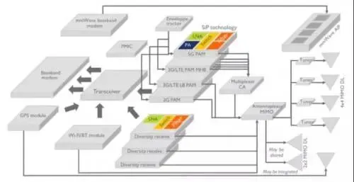
Figure 1: Mobile handset RF system
Challenges for handset RF front-ends
1. Increasing number of supported bands
Compared with 4G handsets that used 2 to 4 antennas, 5G handsets have increased antenna counts to 8–12. The number of supported frequency bands and band combinations has grown significantly, from fewer than 10 bands to dozens of bands. Matching and tuning across bands has become increasingly difficult. From a cost perspective, manufacturers require more expensive 5G test equipment and engineers experienced in 5G testing. While RF tuning for 4G discrete-component handsets typically took less than a week, the increased complexity and integration of 5G RF can extend tuning time by a factor of 3–5. Manual tuning alone cannot meet product iteration schedules. Engineers increasingly need to evaluate system performance early in the design phase using computer-aided simulation to emulate actual signal-path quality and accelerate time to market.
2. Module integration driven by space constraints
The number of RF components scales with antenna count and supported bands, so 5G introduces a sharp increase in RF component count. At the same time, available PCB area allocated to the RF front-end in 5G handsets is limited, and a discrete-component approach consumes more area than available. This drives demand for high-performance, highly integrated modules and challenges automated module modeling workflows. Simulation tools must precisely extract material and structural characteristics and provide convenient, streamlined modeling flows to help engineers accelerate module development.
3. Growing demand for SAW and BAW filters
Each additional supported band typically requires one receive filter and one transmit filter. The large number of new bands in the 5G era has significantly increased the number of filters in mobile devices. Surface acoustic wave (SAW) and bulk acoustic wave (BAW) filters are widely used in handsets because of their low insertion loss, high out-of-band rejection, stable performance, and wide bandwidth, so design demand for SAW/BAW filters continues to grow. Filter design requires many performance targets, and designers must create SAW and BAW filters that meet different specifications for different bands. Historically, there has been a shortage of EDA tools specifically tailored to filter design.
In summary, handset RF front-end design faces multiple challenges: an increased number of supported bands, module integration driven by space constraints, and growing demand for SAW/BAW filters. The following sections describe how Xinhe Semiconductor's handset RF system simulation tools address these issues.
Handset RF system simulation solutions
The RF signal path in handsets typically includes the PCB, active devices (PA, switches, etc.), and passive components (resistors, inductors, capacitors). PCBs have evolved from single- and double-sided boards to high-density multilayer designs, with decreasing trace widths and spacings and increasingly significant electromagnetic effects. PCB layouts are typically generated by EDA tools such as Allegro, PADS, and Zuken. Active device models are usually provided as S-parameter files by vendors, and passive components are supplied by manufacturers such as Murata. Xinhe provides a suite of RF channel quality analysis and optimization tools that include passive electromagnetic extraction, link simulation, and field-circuit co-simulation. Automated simulation workflows increase engineering flexibility.
1. Passive structure modeling and simulation for RF PCBs and modules
In 5G communication systems, the RF channel is critical to communication quality. The XDS toolset integrates a high-accuracy 2.5D full-wave electromagnetic solver that accurately analyzes via and transmission-line effects in RF PCBs. Designers can import layouts from Allegro, PADS, Zuken, and other mainstream tools directly into XDS to create models, and the layout editor supports flexible editing. XDS facilitates quick setup of stackups and materials and can automatically add ports based on component information, simplifying the overall modeling and simulation flow.
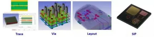
Figure 2: Passive structure modeling in XDS
2. Field-circuit co-simulation
RF systems include transmit (TX) and receive (RX) paths and many components such as power amplifiers, low-noise amplifiers, filters, switches, duplexers, antennas, and passive components. To accurately evaluate link quality, components and the RF PCB must be simulated together in a field-circuit co-simulation. Vendors typically provide S-parameter models for these components for circuit-level simulation. XDS can generate symbols from electromagnetic models and cascade them with component S-parameter models to provide a convenient field-circuit co-simulation workflow.

Figure 3: Field-circuit co-simulation in XDS
3. Optimization of matching and tuning parameters
Due to cost constraints and the difficulty of manual tuning, designers commonly use simulation to find optimal parameter combinations for matching networks. XDS provides a range of optimization modules to support rapid matching design. Features include parametric optimization, objective optimization, design-of-experiments sensitivity analysis, yield statistical analysis, and real-time tuning. These tools help designers quickly optimize component values to find the lowest-cost bill of materials while meeting performance targets, enabling optimal system design. Simulation-driven optimization has become standard practice in product development, and XDS offers multiple analysis tools to help designers identify optimal solutions efficiently.
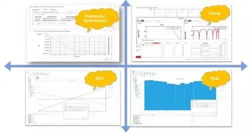
Figure 4: Matching optimization methods in XDS
4. SAW and BAW filter design
Handsets commonly use compact, high-performance surface acoustic wave (SAW) and bulk acoustic wave (BAW) filters. XDS provides an end-to-end SAW/BAW filter design flow. Using method-of-moments and continuum models, the tool offers built-in Ladder and Lattice templates to quickly generate SAW/BAW schematics and extract S-parameters for interdigitated transducers (IDTs), accelerating filter design for the RF front-end.
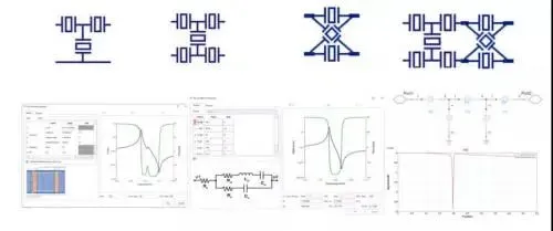
Figure 5: SAW and BAW design workflow with Ladder and Lattice templates
Conclusion
This article summarized key challenges in handset RF front-end design: the growing number of supported bands, module integration driven by limited PCB area, and increased demand for SAW/BAW filters. Xinhe Semiconductor provides simulation tools such as XDS, TmlExpert, and ViaExpert to support passive structure modeling, field-circuit co-simulation, matching optimization, and SAW/BAW filter design. These tools help designers optimize designs, reduce risk, and shorten development cycles.