ALLPCB


Introduction
For NR, waveform design must be improved to efficiently multiplex different services while optimizing for each service's specific requirements.
This article introduces the various candidate waveforms individually.
Single-carrier Waveforms
Single-carrier modulation has been widely used in cellular systems such as GSM, CDMA2000 and UMTS WCDMA. Due to their time-domain symbol ordering, they typically provide low peak-to-average power ratio (PAPR), improving power amplifier (PA) efficiency and extending battery life. This makes single-carrier waveforms particularly suitable for use cases such as mMTC (wide-area IoE), where battery power and extended coverage are primary optimization goals.
On the other hand, single-carrier waveforms suffer link degradation over frequency-selective channels and typically require equalizers to achieve high spectral efficiency in multipath conditions.
Constant-envelope Waveforms
The simplest approach to high transmission efficiency is to use constant-envelope waveforms. This allows almost any PA to operate near saturation without clipping or requiring pre- or post-compensation for clipping. The drawback is reduced capacity efficiency compared with quadrature amplitude modulation (QAM), but for applications that do not require high data rates, constant-envelope waveforms are preferable because they maximize PA efficiency.
Common constant-envelope waveforms include minimum-shift keying (MSK) and Gaussian minimum-shift keying (GMSK), which belong to continuous phase frequency-shift keying (CPFSK) signals. MSK was adopted in the IEEE 802.15.4 standard that provides the physical-layer platform for ZigBee. GMSK has been used in GSM and Bluetooth/Bluetooth Low Energy.
MSK can equivalently be viewed as offset QPSK with sinusoidal pulse shaping, which enables effective modulation and demodulation. Note that a differential encoder is inserted before the modulator to avoid error propagation at the demodulator. This also simplifies the modulator because the differential encoder and differential decoder cancel each other.
GMSK is a variant of MSK in which a Gaussian-filtered version of the information sequence is applied to the MSK modulator. The Gaussian filter improves spectral efficiency and reduces intersymbol interference. With Gaussian filtering, a GMSK signal can no longer be seen as offset QPSK. Typical GMSK receivers use a linear approximation of the GMSK pulse and treat the modulation as a sum of pulse-amplitude modulation (PAM) signals. With that approximation, a Viterbi detector can be used. Note that lower-complexity GMSK demodulators are commonly used in low-power devices like Bluetooth LE.
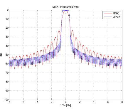
Figure 1: MSK PSD
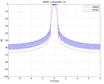
Figure 2: GMSK PSD
Single-carrier QAM
As noted, higher-order QAM can be used to achieve higher spectral efficiency for single-carrier waveforms. The most common waveform used in 3G networks (for example UMTS, CDMA2000, 1xEV-DO) is single-carrier CDMA with QAM modulation.
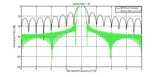
When QPSK modulation is selected, it gives a constant-amplitude waveform with 0 dB PAPR. In practice, transmission is usually followed by time-dispersive, frequency-localized pulse-shaping filters in the frequency domain to reduce out-of-band (OOB) leakage and meet adjacent channel leakage ratio (ACLR) requirements. Figure 3 illustrates the power spectral density (PSD) of single-carrier QPSK modulation with and without transmit pulse shaping.
Consequently, matched filtering is implemented at the receiver to maximize SNR. To eliminate intersymbol interference (at least for frequency-flat channels), pulse-shaping filters are typically chosen as half-Nyquist filters, so that the cascade of transmit and receive filters has Nyquist characteristics. Specifically, Figure 3 plots the PSD for root-raised-cosine filters with a roll-off factor, as used in WCDMA.
Note that with transmit pulse shaping the transmit waveform is no longer constant envelope and PAPR > 0 dB. Figure 4 illustrates PSDs of single-carrier QPSK with different clipping thresholds relative to the average power. Figure 6 shows the corresponding EVM for different clipping thresholds.
Some enhancements can be applied to further reduce PAPR, such as pi/4–QPSK, which introduces a pi/4 rotation between even and odd constellations to avoid any path through the origin (zero crossings). In UMTS, HPSK scrambling removes any path through the original chip for certain chip index pairs. This method relies on symbol expansion with at least a factor of 2.
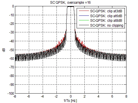
Figure 5 compares the PAPR of several single-carrier waveforms with QPSK modulation. Some of these waveforms are discussed later. This section explains the observations in Figure 6, where single-carrier QPSK gives lower EVM compared with DFT-spread OFDM waveforms.
Note that the PAPR and clipping shown here do not reflect multiuser multiplexing, such as code-division multiplexing.
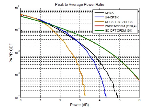
Figure 5: PAPR of single-carrier waveforms
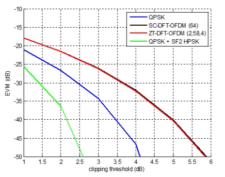
Figure 6: EVM of single-carrier waveforms
Two natural methods to achieve wider bandwidth are to increase the sampling rate or to provide separate single carriers on adjacent channels. As Figures 2 and 4 show, pulse-shaping filters can be designed to provide sufficient adjacent-channel suppression so that each channel can reach its peak rate. The latter approach is the basis of 3G multi-carrier approaches, for example EV-DO Rev B or dual-carrier HSDPA.
In multipath fading, an important aspect of achieving higher spectral efficiency with single-carrier QAM is the use of effective equalization algorithms. This often depends on receiver design and available implementation complexity. Although well-known time-domain algorithms exist, such as fractionally spaced equalizers, RAKE and adaptive equalizers, there is a common misconception that computationally efficient frequency-domain equalization belongs only to OFDM waveforms.
In fact, single-carrier waveforms can be implemented with frequency-domain equalization, and constructions that include a cyclic prefix for block-based transmission are formally known as SC-FDE. This scheme is shown in Figure 7. The 802.11ad standard, a 60 GHz unlicensed millimeter-wave technology, includes such a waveform, and commercial implementations have been released by Qualcomm Atheros.
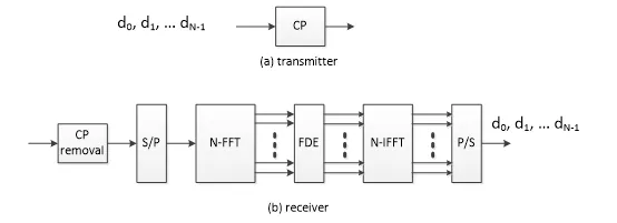
Figure 7: SC-FDE modulator and demodulator
In summary, SC-FDE has similar pros and cons to SC-QAM, with the added advantage of a convenient frequency-domain equalizer implementation at the receiver, at the cost of spectral efficiency loss due to the cyclic prefix.
DFT-spread OFDM
A variant of SC-FDE is DFT-spread OFDM, where the time-domain QAM symbols undergo an M-point DFT. The M-point DFT outputs are mapped onto a larger IFFT so that different sets of tones modulate that IFFT, which then converts the signal back to the time domain. If M equals the IFFT size, the scheme reduces to original SC-FDE.
The main purpose of DFT-spread OFDM is to provide flexibility in frequency-domain orthogonal allocation of varying bandwidths to multiple users. When combined with frequency multiplexing this is commonly called SC-FDMA. Two common allocation methods in SC-FDMA are:
- Localized SC-FDMA (LFDMA): contiguous subcarriers are allocated to each user. An example is LTE uplink data and uplink control channels.
- Interleaved SC-FDMA (IFDMA): non-contiguous subcarriers evenly distributed over the band are allocated to each user. Although not contiguous, the equal spacing preserves the IFFT output as a single-carrier waveform. An example is LTE uplink reference signals.
Because the subcarriers allocated to a user span the whole band, IFDMA can achieve better frequency diversity than LFDMA. However, depending on channel coherence bandwidth, channel interpolation in IFDMA may be more challenging.
As with SC-FDE, adding a cyclic prefix to the waveform allows straightforward implementation of a frequency-domain equalizer at the receiver. M-point DFT precoding helps preserve single-carrier characteristics after the N-point OFDM used for synthesis, resulting in lower PAPR than conventional OFDM. Reduced PAPR can translate to better efficiency if the PA runs with less back-off, although other waveforms may be more favorable.
Another advantage of SC-FDMA is low inter-carrier interference when tight synchronization is present. Mathematically, each M-point DFT's set of subcarriers has zeros at the subcarriers used by any other M-point DFT, so inter-carrier interference becomes zero under perfect synchronization. For other frequency-domain multiplexing schemes that use root-raised-cosine filtering to separate adjacent subchannels, this is not always the case. Note that because SC-FDMA is a block-based waveform, there will be discontinuities between blocks. These can be mitigated with weighted overlap-and-add (WOLA), which improves emissions as shown in Figure 8.
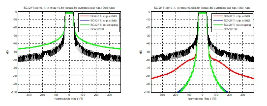
Figure 8
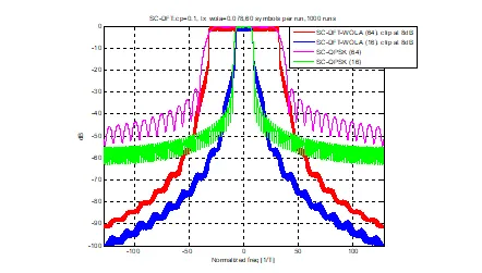
Figure 9
Zero-tail DFT-OFDM
The main variation in zero-tail DFT-spread OFDM is that the usual cyclic prefix is replaced by zero symbols appended to the DFT-precoded data input, as shown in Figure 10.
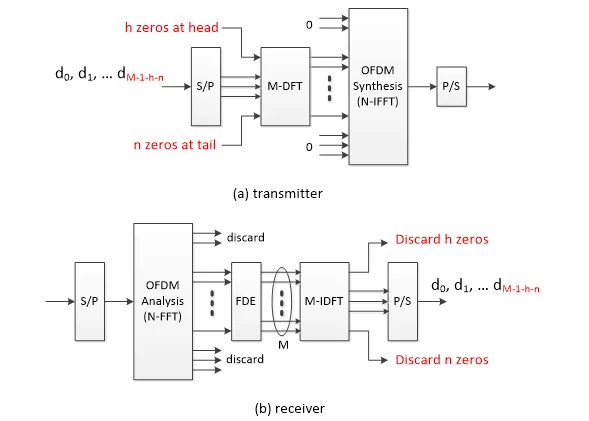
Figure 10
Zero-tail insertion has several advantages:
- The zero-tail length can be variable depending on each user's channel delay spread and propagation delay, rather than a fixed cyclic prefix length for the entire network, which may reduce overhead for some users.
- OOB leakage can be suppressed by zero padding, smoothing transitions between adjacent symbols.
- Zero-tail can potentially reduce overhead related to RF beam switching.
Compared with DFT-spread OFDM, zero-tail protection optimization can provide slight link-performance improvements. In practice, simply changing CP or protection is not sufficient to handle all delay spreads; subcarrier spacing (and therefore block length) must also be scaled to optimally handle delay spread and channel characteristics. For the same block size and subcarrier spacing, and considering LTE CP overhead, zero-tail protection may benefit up to about 7%. There is additional signaling overhead to support zero-tail and increased control-loop complexity.
Figures 5 and 6 compare PAPR and EVM of ZT DFT-spread OFDM with other single-carrier waveforms. Note that the IFFT oversampled portions corresponding to inserted zero tails are not part of the useful signal and are excluded from average power calculations. As expected, ZT DFT-spread OFDM yields PAPR and EVM comparable to conventional DFT-spread OFDMA.
Figure 11 compares the PSD of ZT DFT-spread OFDM with single-carrier QPSK. It is worse by more than 50 dB in some regions but decays faster below -50 dB. Compared with SC-FDMA in prior figures, the behavior is reversed.
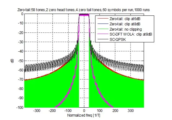
Figure 11
OFDM-based Multicarrier Waveforms
Multicarrier waveforms can generally be expressed as a sum of modulated subcarriers. Although this looks similar to schemes such as DC-HSDPA, here subcarriers may overlap in frequency with adjacent subcarriers but are actually zero when sampled at the subcarrier frequencies in the frequency domain. The most commonly deployed version of this approach is OFDM, so we refer to these as OFDM-based multicarrier waveforms.
CP-OFDM
CP-OFDM is the most widely used multicarrier waveform in current broadband wireless standards, including 3GPP LTE and IEEE 802.11, because of several attractive properties:
- Efficient implementation using FFT/IFFT
- Direct application of MIMO in frequency-selective channels by using a cyclic prefix
- Simple frequency-domain equalization per subcarrier for non-flat channels
- Dynamic bandwidth allocation to users
CP-OFDM can be synthesized as a special case by setting the prototype filter p(n) to a rectangular pulse and bypassing b(n). This simplification allows efficient implementation with FFT and IFFT for the modulator and demodulator.
An early advantage of OFDM over single-carrier methods was better link performance in frequency-selective fading channels. However, with advances in receiver design, SC-FDE and related variants can perform comparably, even before considering PA nonlinearity. Another important difference is that OFDM offers flexible signal and user multiplexing across the time-frequency grid, which is important for features like MIMO spatial multiplexing. For example, pilot placement for channel estimation can be more flexible across the OFDM time-frequency grid than in single-carrier schemes. Without spatial multiplexing, single-carrier and DFT-spread OFDM may be better suited for scheduling low-order modulations (for example QPSK) from power-limited devices.
A reported disadvantage of CP-OFDM without additional transmit processing (for example WOLA) is poor frequency localization due to the rectangular prototype filter. Slow-decaying OOB leakage can interfere with adjacent bands and cause in-band interference if there is frequency offset between users. Figure 14 shows the PSD of a CP-OFDM waveform with 12 contiguous data tones and a CP length of about 10% of the OFDM symbol duration. The PAPR is significantly higher than for single-carrier waveforms.
CP-OFDM with WOLA
In CP-OFDM with weighted overlap-and-add (WOLA), the rectangular prototype filter is replaced by a pulse with soft edges on both sides, leading to sharper sidelobe decay in the frequency domain. The soft edges at the start and end of the filter effectively provide better spectral containment than the conventional rectangular filter used in CP-OFDM. Thus, CP-OFDM with WOLA is a special case with an improved prototype filter p(n) that has a better frequency response and a bypass b(n).
In practice, better frequency containment is obtained by applying time-domain windowing to add soft edges to the cyclicly extended OFDM symbol. Although edges extend each symbol, overhead remains the same as CP-OFDM because adjacent symbols overlap in the transition regions. The shape of the window determines the prototype filter frequency response; there is a tradeoff between mainlobe width and sidelobe suppression. Raised-cosine edges are a practical compromise.
Figure 14 illustrates the PSD of transmit CP-OFDM with WOLA. OOB suppression is clearly improved compared with CP-OFDM. The PAPR of CP-OFDM with Tx WOLA is comparable to conventional CP-OFDM, as shown in Figure 21.
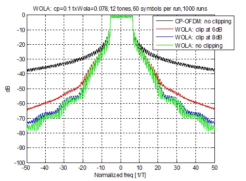
Figure 14
In addition to applying WOLA at the transmitter to reduce OOB leakage, WOLA can also be applied at the receiver to suppress interference from other users. When users are asynchronous, applying soft edges at the receiver reduces interference caused by mismatched FFT capture windows. An Rx WOLA processing diagram is shown in Figure 15.
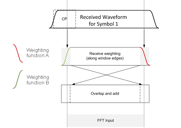
Figure 15
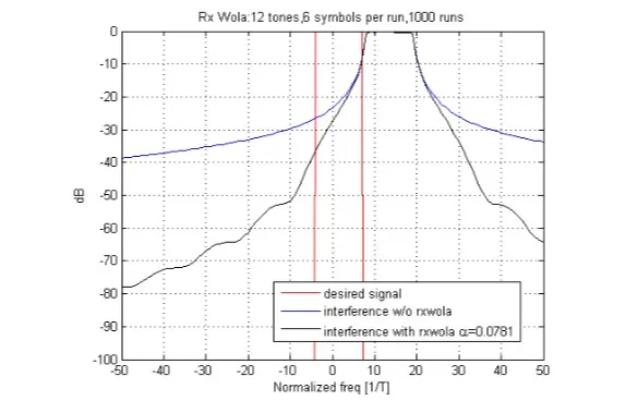
To demonstrate Rx WOLA's effect in suppressing asynchronous user interference, the OOB leakage from 16 adjacent interferers was compared with random frequency offsets. In simulations, two users with 12 tones each were adjacent and the FFT capture window aligned with the desired user. Random offsets were inserted between the two users and the interferer's PSD was averaged over 1000 runs. As Figure 16 shows, interference from asynchronous adjacent users is significantly reduced when Rx WOLA is used.
UFMC
Like WOLA, Universal Filtered Multicarrier (UFMC) aims to reduce OOB leakage. While WOLA uses raised-cosine prototype filtering, UFMC introduces nontrivial bandpass filtering b(n). Figure 17 shows the UFMC modulator and demodulator.
Transmitter operation is illustrated in Figure 18. IFFT symbol generation is the same as conventional CP-OFDM. Instead of a cyclic prefix, a zero-filled guard interval (GI) is introduced between IFFT symbols to prevent ISI due to tx filter delay. Symbols are then processed by the tx filter b(n) and transmitted. Typically, the tx filter length is set equal to the GI duration.
Figure 19 shows receiver operation. Because UFMC uses GI instead of CP, UFMC lacks the cyclic convolution property. The receiver structure is therefore not as straightforward as CP-OFDM. Unlike a CP-OFDM receiver that discards CP, the UFMC receiver uses the entire symbol including GI. For this, a 2x-size FFT is used at the receiver, but only the even outputs of the 2x-size FFT are used for detection.
Viewed in the context of Figure 12, UFMC can be summarized as follows:
- The prototype filter is a rectangular pulse followed by a zero interval; the zero interval represents the guard interval between symbols and the rectangular part corresponds to the IFFT symbol.
- The tx filter b(t) is carefully designed to suppress OOB interference. The filter taps of b(t) are typically set equal to the GI length.
- To confine OOB interference, the tx filter must be designed as a bandpass filter that passes only the specified resource block (RB). When each RB consists of the same number of contiguous tones, the same filter can be reused by shifting the center frequency. The transmitter block diagram in Figure 17 shows parallel IFFT and tx filter operations for each RB.
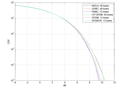
Figure 21: PAPR for different modulation schemes
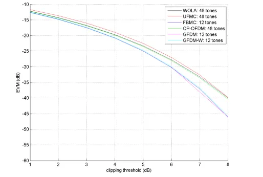
Figure 22: EVM for different modulation schemes
FCP-OFDM
A scheme similar to UFMC is flexible CP-OFDM (FCP-OFDM). The main difference from UFMC is that the whole zero-padding is partitioned into zero-padding and cyclic prefix with flexible partitioning. The motivation is to provide a flexible tradeoff between multipath handling and OOB emission suppression.
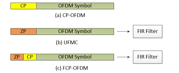
The figure illustrates symbol-structure differences among conventional CP-OFDM, UFMC and FCP-OFDM. Due to the similarities between FCP-OFDM and UFMC, their symbol structures are comparable.