ALLPCB


Introduction
Flexible printed circuit boards, or flex PCBs, play a critical role in modern automotive electronics by enabling compact, lightweight interconnects in space-constrained areas. These circuits conform to irregular shapes and dynamic movements found in vehicles, such as sensor arrays and lighting modules. Automotive environments demand exceptional reliability due to extreme temperatures, constant vibrations, moisture, and chemical exposure. Engineers designing flexible PCB automotive solutions must prioritize materials and layouts that withstand these conditions without failure. This article explores design strategies to ensure automotive flex circuit reliability, focusing on high-temperature flex PCB and vibration resistant flex PCB capabilities. By adhering to established engineering principles, designers can achieve long-term performance in demanding applications.
Understanding Flexible PCBs in Automotive Contexts
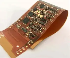
Flexible PCBs consist of thin conductive traces laminated onto flexible substrates, typically polyimide or polyester films, allowing bending and twisting without breaking. In automotive use, they connect components in engines, transmissions, and chassis where rigid boards cannot fit. Flexible PCB for car sensors, for instance, routes signals from accelerometers and proximity detectors in tight assemblies. Automotive lighting flex PCB supports dynamic LED arrays in headlights and taillights that require repeated flexing during adjustments. Reliability becomes paramount as failures can lead to safety issues or costly recalls. These circuits must endure cycles of thermal expansion, mechanical stress, and environmental assaults over the vehicle's lifespan.
The shift toward electric vehicles and advanced driver-assistance systems amplifies the need for robust flexible PCB automotive designs. Sensors for battery management and autonomous driving generate high data volumes through slim interconnects. Vibration from road conditions and engine operation tests the mechanical integrity of traces and vias. High-temperature zones near exhausts or power electronics push material limits. Designers balance flexibility with durability to meet functional requirements. Proper selection ensures seamless integration into harsh automotive ecosystems.
Key Challenges: Harsh Environments and Their Impact on Flex Circuits
Automotive applications expose flexible PCBs to temperature swings from -40°C to over 125°C, causing substrate expansion and trace cracking if materials lack thermal stability. Polyimide substrates excel here due to high glass transition temperatures, maintaining integrity during heat cycles. Vibration induces fatigue in copper traces, leading to microcracks at bend points without adequate radius control. Chemical agents like oils and salts accelerate delamination at interfaces. Moisture ingress promotes corrosion in unprotected areas. Engineers must model these stressors using finite element analysis to predict failure modes.
High-temperature flex PCB designs face additional hurdles from solder joint degradation and adhesive softening. Repeated thermal cycling per IPC-6013 qualification tests reveals weaknesses in layer adhesion. Vibration resistant flex PCB requires reinforced anchor points to distribute mechanical loads evenly. Dynamic bending in moving parts, such as deployable antennas, amplifies strain on conductors. Humidity combines with temperature to swell substrates, altering electrical performance. Comprehensive understanding of these interactions guides resilient designs.
Material Selection for Enhanced Reliability
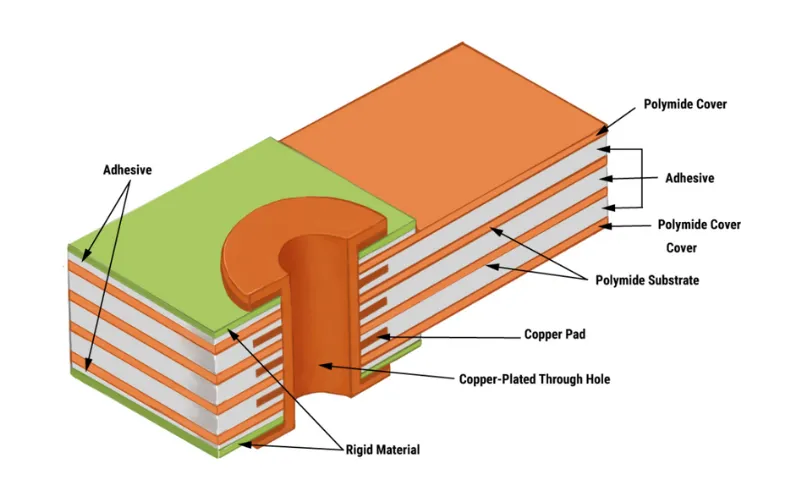
Choosing the right substrate forms the foundation of automotive flex circuit reliability. Polyimide offers superior thermal resistance, with continuous operation up to 200°C and short excursions higher, ideal for engine compartments. Coverlays and adhesives must match this stability to prevent peeling under stress. Copper foil thickness influences bend endurance; thinner foils reduce stiffness but demand precise etching to avoid necking. Covercoat materials protect against abrasion and chemicals prevalent in under-hood environments. Material datasheets provide key metrics like coefficient of thermal expansion for matching with components.
For vibration resistance, rolled annealed copper provides better ductility than electrodeposited types, resisting fatigue cracks. Stiffeners made from polyimide or FR-4 reinforce rigid sections without compromising flexibility. Adhesive choice affects peel strength, critical during shock events. Engineers evaluate combinations through bend and thermal shock tests. High-reliability grades ensure compliance with performance classes in IPC-6013. This systematic approach minimizes field failures.
Design Principles for Vibration and Thermal Endurance
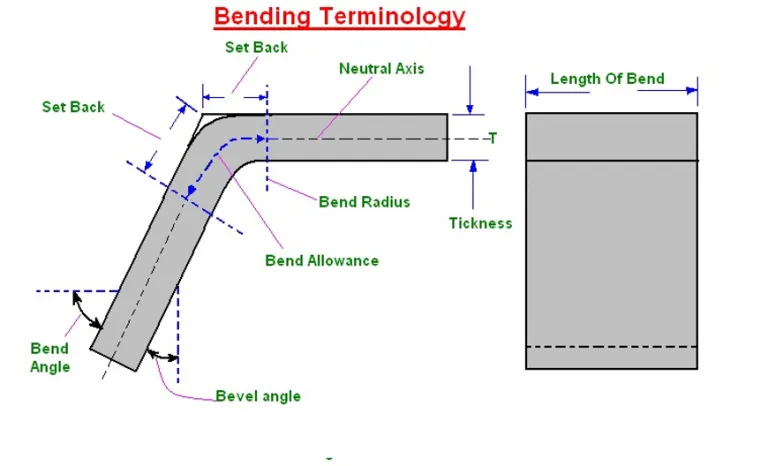
Trace routing in flexible PCB automotive layouts follows minimum bend radii to prevent stress concentrations, typically 10 times the copper thickness for dynamic flexing. Avoid acute angles; use teardrop transitions at pads to distribute strain. Vias placement away from bend zones reduces cracking risks during vibration. For multilayer stacks, staggered traces align with the neutral bending axis. Signal integrity demands controlled impedance, especially for high-speed sensor data. Ground planes shield against electromagnetic interference from vehicle motors.
Automotive lighting flex PCB benefits from serpentine routing patterns that elongate under flex, absorbing deformation. Anchor tabs secure ends to housings, limiting free-floating sections prone to whipping. Strain relief features like slotted holes accommodate thermal growth. Simulation tools verify dynamic responses under sinusoidal vibrations per relevant test methods. These principles enhance automotive flex circuit reliability across applications.
IPC-2223 provides guidelines for sectional design, emphasizing coverlay margins and overlap for robust interconnections. Compliance ensures predictability in production scaling.
Qualification and Testing Best Practices
Reliability validation starts with qualification testing aligned with IPC-6013 performance specifications. Thermal cycling from -65°C to 125°C assesses adhesion and electrical continuity after thousands of cycles. Vibration testing applies random profiles simulating road profiles, monitoring resistance changes. Bend endurance tests flex circuits to specified radii and cycles, quantifying fatigue life. High-temperature storage bakes boards to accelerate aging effects. Cross-section analysis post-test reveals delamination or cracking.
For flexible PCB for car sensors, combine environmental chambers with functional testing under power. Solder joint integrity requires shear and pull tests after exposure. Dimensional stability checks warpage via shadow moire. Data logging captures intermittent failures. Iterative design refines weak points. This rigorous process builds confidence in harsh deployments.
Integration Strategies and Common Pitfalls
Successful flexible PCB automotive integration involves mechanical modeling of assembly tolerances. Over-constraining flex tails leads to trace tears; allow float in connectors. Component placement on rigid-flex hybrids considers flex-to-rigid transitions. Shielding layers mitigate noise in sensor chains. Pitfalls include ignoring coverlay shrinkage, causing trace exposure, or undersizing pads for wave soldering. Proactive DFMEA identifies risks early.
In high-temperature flex PCB, preheat profiles prevent voids in adhesives. Vibration resistant flex PCB uses epoxy potting for added damping in critical zones. Field data from prototypes informs refinements. Collaborative reviews with manufacturing ensure producibility.
Conclusion
Designing flexible PCBs for automotive applications demands a holistic approach to reliability in harsh environments. Material choices like polyimide, combined with precise routing and reinforcement, address thermal and vibrational stresses effectively. Standards such as IPC-6013 and IPC-2223 guide qualification, ensuring consistent performance. Best practices in testing and integration mitigate common failures, enabling applications from sensors to lighting. Electrical engineers can leverage these strategies to deliver robust solutions that enhance vehicle safety and longevity. Future advancements will further push flex circuit boundaries in electrified mobility.
FAQs
Q1: What materials ensure high-temperature flex PCB performance in automotive engines?
A1: Polyimide substrates provide the thermal stability needed for engine bay flexible PCB automotive use, with high glass transition temperatures resisting degradation up to 200°C continuously. Select rolled annealed copper for traces to maintain ductility under heat cycles. Matching adhesives and coverlays prevent delamination. Qualification per IPC-6013 verifies endurance. This combination supports reliable operation near hot components.
Q2: How do you achieve vibration resistant flex PCB in car chassis sensors?
A2: Design with minimum bend radii and strain relief features to distribute mechanical loads evenly across flexible PCB for car sensors. Use anchor tabs and stiffeners to secure against whipping. Serpentine traces absorb deformation without cracking. Vibration testing simulates road profiles, monitoring continuity. Adhering to IPC-2223 guidelines optimizes layout for dynamic environments.
Q3: Why is automotive flex circuit reliability critical for lighting applications?
A3: Automotive lighting flex PCB must withstand repeated flexing and thermal swings from LED heat without signal loss. Failures disrupt visibility, posing safety risks. Robust design with protective coverlays and impedance control ensures integrity. Environmental testing confirms performance over vehicle life. Proper integration enhances system dependability.
Q4: What design rules improve automotive flex circuit reliability overall?
A4: Follow trace width spacing for current handling and bend zones avoidance for vias. Incorporate ground shielding and teardrop pads to reduce stress. Model thermal expansion mismatches early. Iterative testing refines prototypes. These practices align with industry standards for harsh condition survival.