 ALLPCB


If you're looking to improve the efficiency and yield of your surface mount technology (SMT) assembly process, following Design for Assembly (DFA) guidelines is key. These guidelines help streamline production, reduce errors, and ensure high-quality results by optimizing every step from design to manufacturing. In this comprehensive guide, we'll dive into essential DFA practices for SMT assembly, covering stencil design, component orientation, reflow soldering, and solder paste application. Whether you're a seasoned engineer or new to PCB design, these actionable tips will help you achieve better outcomes in your projects.
What is DFA in SMT Assembly?
Design for Assembly (DFA) refers to the practice of designing products in a way that makes them easier and more cost-effective to assemble. In the context of surface mount technology (SMT), DFA focuses on creating PCB layouts and assembly processes that minimize errors, reduce production time, and improve overall yield. By integrating DFA principles early in the design phase, you can avoid costly rework and ensure a smoother transition from prototype to mass production.
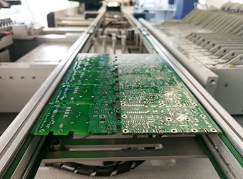
SMT assembly involves placing tiny components directly onto the surface of a printed circuit board (PCB), a process that demands precision and attention to detail. DFA guidelines for SMT help address common challenges like misalignment, soldering defects, and inefficient workflows. Let’s explore the critical areas where DFA can make a significant impact.
Why DFA Matters for SMT Assembly Efficiency and Yield
In SMT assembly, even small design oversights can lead to big problems during production. Misaligned components, poor soldering, or inefficient layouts can result in defects, increased costs, and delays. DFA guidelines aim to prevent these issues by optimizing the design for automation and repeatability. According to industry studies, over 60% of soldering defects in SMT assemblies originate during early design or process stages like solder paste printing. By following DFA best practices, you can significantly reduce these risks and achieve a higher first-pass yield.
Efficiency is another major benefit. DFA helps reduce assembly time by simplifying processes, which is especially important in high-volume production. A well-designed PCB that adheres to DFA principles can cut down on manual adjustments and machine downtime, ultimately saving time and resources.
Key DFA Guidelines for SMT Assembly
Let’s break down the core DFA guidelines for SMT assembly, focusing on specific areas that impact efficiency and yield. Each section below provides practical tips and examples to help you implement these practices effectively.
1. Stencil Design for SMT: Precision in Solder Paste Application
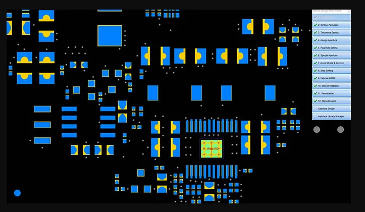
Stencil design is a critical aspect of SMT assembly because it directly affects how solder paste is applied to the PCB. Poor stencil design can lead to uneven paste distribution, resulting in weak solder joints or bridging. Here are some DFA tips for optimizing stencil design:
- Match Aperture Size to Pad Size: Ensure that the stencil apertures (openings) are slightly smaller than the PCB pads, typically by 10-20%, to prevent excess paste and reduce the risk of bridging. For example, a pad measuring 0.5 mm x 0.3 mm might have an aperture of 0.45 mm x 0.27 mm.
- Use Proper Thickness: Choose a stencil thickness based on the component types. For fine-pitch components (e.g., 0.4 mm pitch), a thinner stencil of 0.1 mm to 0.12 mm is ideal. For larger components, a thickness of 0.15 mm to 0.2 mm may be better to ensure adequate paste volume.
- Incorporate Fiducial Marks: Add fiducial marks on the stencil and PCB for precise alignment during printing. These marks help automated machines calibrate their position, reducing errors.
By focusing on these stencil design principles, you can achieve consistent solder paste application, which is the foundation of reliable SMT assembly.
2. Component Orientation in SMT: Streamlining Placement
Component orientation is another crucial factor in DFA for SMT assembly. Proper orientation ensures that automated pick-and-place machines can work efficiently without frequent adjustments or errors. Here are some guidelines to follow:
- Standardize Orientation: Orient similar components in the same direction whenever possible. For example, align all diodes or capacitors with their polarity markers facing the same way to minimize machine reprogramming and reduce placement errors.
- Avoid Rotational Complexity: Limit the number of different angles for component placement. Ideally, stick to 0° and 90° orientations to simplify the pick-and-place process. Complex angles like 45° can slow down assembly and increase the risk of misalignment.
- Provide Clear Markings: Include silkscreen markings on the PCB to indicate polarity or orientation for components like LEDs and ICs. This helps during both automated assembly and manual inspection.
By optimizing component orientation, you can enhance the speed and accuracy of the assembly process, ultimately boosting efficiency.
3. Reflow Soldering DFA: Ensuring Strong Connections
Reflow soldering is the process of melting solder paste to create permanent connections between components and the PCB. DFA guidelines for reflow soldering focus on creating conditions for consistent, defect-free results. Here are key considerations:
- Optimize Thermal Profiles: Develop a reflow soldering temperature profile tailored to your components and solder paste type. For lead-free solder, a typical profile includes a preheat stage (150-180°C for 60-90 seconds), a soak stage (180-200°C for 60-120 seconds), and a reflow peak (235-250°C for 20-40 seconds). This prevents thermal shock and ensures proper solder melting.
- Balance Pad Sizes: Design pads with balanced copper areas to avoid uneven heating during reflow. For instance, if one side of a component pad connects to a large ground plane, add thermal reliefs to prevent heat dissipation issues that could cause tombstoning (components standing on end).
- Minimize Component Density: Avoid overcrowding components in high-density areas, as this can lead to uneven heat distribution and poor solder joints. Leave at least 0.3 mm spacing between small components for better heat flow.
Following these DFA tips for reflow soldering can help you achieve strong, reliable connections while minimizing defects like cold joints or bridging.
4. Solder Paste Application DFA: Laying the Groundwork for Success
Solder paste application is often the starting point for SMT assembly, and errors at this stage can cascade into larger issues. DFA guidelines for solder paste application aim to ensure uniformity and precision. Consider these best practices:
- Use Consistent Paste Volume: Calculate the required solder paste volume based on pad size and component type. For a 0402 resistor, a paste volume of around 0.0003 cubic millimeters is typical. Adjust stencil apertures and printing parameters to achieve this consistently.
- Control Printing Speed and Pressure: Set the solder paste printer to operate at a moderate speed (20-50 mm/s) and apply uniform pressure on the squeegee to avoid smearing or insufficient paste deposition.
- Inspect After Printing: Use automated optical inspection (AOI) to check for defects like insufficient paste or misalignment immediately after printing. Catching issues early prevents costly rework later in the process.
By prioritizing precision in solder paste application, you create a solid foundation for the rest of the SMT assembly process.
Additional DFA Tips for SMT Assembly Success
Beyond the core areas discussed above, here are a few more DFA guidelines to enhance your SMT assembly process:
- Simplify Component Selection: Use standardized components with readily available footprints to reduce assembly complexity and sourcing issues. Avoid exotic or hard-to-source parts unless absolutely necessary.
- Design for Testability: Include test points in your PCB layout to facilitate in-circuit testing (ICT) after assembly. Place test points on a grid with at least 2.5 mm spacing for probe access.
- Document Clearly: Provide detailed assembly drawings and bill of materials (BOM) with clear notes on component placement, orientation, and soldering requirements. This reduces ambiguity during production.
These additional practices can further streamline your workflow and improve the overall yield of your SMT assembly projects.
Benefits of Implementing DFA Guidelines in SMT Assembly
Adopting DFA guidelines for SMT assembly offers several tangible benefits:
- Higher Yield: Reducing design-related defects leads to a higher percentage of usable boards after the first pass, saving time and materials.
- Lower Costs: Streamlined processes and fewer errors mean less rework and lower production costs.
- Faster Turnaround: Optimized designs and assembly processes speed up production, helping you meet tight deadlines.
- Improved Quality: Consistent application of DFA principles results in reliable, high-performance PCBs that meet customer expectations.
By focusing on DFA from the start, you set the stage for success in every aspect of SMT assembly.
Common Challenges in SMT Assembly and How DFA Solves Them
SMT assembly comes with its share of challenges, but DFA provides practical solutions. Here are some common issues and how DFA guidelines address them:
- Challenge: Component Misalignment - DFA Solution: Standardize component orientation and use fiducial marks for precise machine alignment.
- Challenge: Soldering Defects - DFA Solution: Optimize stencil design and reflow profiles to ensure uniform solder paste application and melting.
- Challenge: High Rework Rates - DFA Solution: Design for testability and inspect at key stages to catch issues early.
By proactively addressing these challenges through DFA, you can minimize disruptions and maintain a smooth production flow.
Conclusion: Elevate Your SMT Assembly with DFA Guidelines
Implementing DFA guidelines for SMT assembly is a game-changer for boosting efficiency and yield. From optimizing stencil design and component orientation to refining reflow soldering and solder paste application, each step plays a vital role in creating high-quality PCBs with minimal errors. By incorporating these best practices into your design and manufacturing processes, you can save time, reduce costs, and deliver reliable products that meet the highest standards.
Start applying these DFA tips in your next project to see the difference they make. With a focus on precision and efficiency, you’ll be well on your way to mastering SMT assembly and achieving outstanding results.


