 ALLPCB


Introduction
Many developers who write firmware and software for embedded systems often want to start coding immediately, neglecting or spending little time on the critical program design phase. This tendency is more pronounced in our field than in others.
For example, a builder or a hardware engineer would never start construction without fully developed blueprints or schematics. By contrast, firmware developers frequently go straight to coding without fully developing program logic, which often produces tangled, "spaghetti" code.
Developing code before completing the design usually leads to disorganized programs and wasted effort.
Why predesign matters
Developers fall into three common patterns:
- They try to design and code at the same time, a method sometimes called "design a little, code a little."
- They rely excessively on the constraints of the programming language while developing program logic.
- They skip the design step entirely because they think the project is "too simple" or they are overconfident in their abilities.
This rush to write code can be counterproductive and ultimately consume more development time, since poorly designed programs may contain many errors that careful planning could have avoided.
If you use the "design a little, code a little" approach, you may need to erase or retype large portions of code as the design evolves. The program may end up twice as long and half as efficient as it should be. Skipping the design phase on the assumption that it will speed development and that the embedded system will immediately work is often a costly mistake.
In fact, building compact code for microcontrollers requires spending time designing the program systematically before writing a single line of code. This practice, known as structured programming, produces code that uses less memory, requires less processing time, and often works correctly on the first try.
Structured programming requires a thorough understanding of the problem. It uses top-down analysis to break the problem into increasingly smaller parts until each part has an obvious solution or function. It also uses three control structures—sequence, selection, and repetition—to organize or combine functions.
One popular tool for designing programs in structured programming is the Warnier-Orr diagram, named after its creators Jean-Dominique Warnier and Kenneth T. Orr.
What is a Warnier-Orr diagram
Warnier-Orr diagrams were created as a visual tool to show the hierarchical decomposition of complex data or processes. Their main purpose is to represent program logic structure.
A program is an ordered set of instructions that processes input data to produce results. A microcontroller is an information-processing device. Input data, results, and the program itself are information structures that can be nested and organized hierarchically.
Warnier-Orr diagrams let you define the required outputs and work backwards to break down the inputs and processing steps needed to produce those outputs. They help represent, graphically, the hierarchy of program steps and the decomposed input and output data structures.
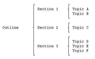
Warnier-Orr diagram overview and notation
- Warnier-Orr diagrams use brackets to draw program or data structures horizontally on the page.
- Within the brackets, Warnier diagrams are read left to right, top to bottom.
- For program structure, each bracket serves as a visual cue representing a completed subroutine in the program.
- If an item or function has the symbol (0,1) below it, it indicates presence or absence, selection or nonselection, or false or true.
- The symbol + denotes inclusive OR. If two or more items or steps inside a bracket are separated by "+", it means one or the other or both may be included.
- The symbol ? denotes exclusive OR. If items or steps inside a bracket are separated by "?", it means one or the other is included or executed, but not both.
- The notation (n,N) indicates how many times a function will be executed.
- When representing a program, each level or subfunction consists of three parts: start, process steps, and end.
With the Warnier-Orr tool, you can design the program for your next embedded project.
Steps for logical design of microcontroller programs
Building a good microcontroller program requires a systematic approach. Jean Warnier and other authors describe four design steps that guide program development.
Step 1: Identify outputs
The first and most important step is to determine the outputs the program must produce. Ask yourself, "What do I want the program to do?" Answer this as clearly as possible.
Step 2: Define the logical data base
Once the outputs are clearly defined, identify the required inputs and define the attributes of those inputs. This step helps ensure all necessary inputs are considered and prevents later omissions such as "Oops, I forgot an input." Keep the scope under control.
When you can answer the questions in steps 1 and 2, you have completed the preliminary design.
Step 3: Design the program structure
Designing the program structure is done in two phases: top-down analysis and synthesis.
Top-down analysis breaks the program into more detailed subfunctions. Start with a single block describing the overall function and progressively expand that block into detailed subfunctions. During this phase, you do not need to worry about the execution order of subfunctions. Focus on what should be done, not how to do it.
Since much of this is intuitive, proceed slowly and avoid developing too many details too quickly.
After completing top-down analysis, you will have a set of basic components. Synthesis involves deciding the order in which functions should be executed. The three basic logical structures for organizing these functions are sequence, if-then-else, and loop. Combinations of these structures can be used to build complex functions.
Step 4: Represent your design with a Warnier-Orr diagram
Use a Warnier-Orr diagram to convert your design into an outline. The entire diagram should contain only logical statements, not code. This makes the documentation easier to understand.


