ALLPCB


Introduction
Selecting the appropriate components for a power supply PCB is critical to ensuring reliable operation, efficiency, and longevity in demanding applications. Power supply circuits handle high currents, voltages, and thermal stresses, making power supply PCB components selection a foundational step in the design process. Engineers must balance performance metrics like ripple suppression, load regulation, and transient response with practical constraints such as size, cost, and availability. Poor choices can lead to failures like overheating, voltage instability, or premature component degradation. This article explores key considerations for capacitors, resistors, diodes, and other essentials, providing structured guidance tailored for electrical engineers. By following engineering principles and industry standards, designers can optimize their power supply PCB for real-world robustness.
Why Power Supply PCB Components Matter
Power supply PCBs serve as the backbone of electronic systems, converting and regulating electrical power for everything from consumer devices to industrial equipment. Components in these circuits endure continuous stress from switching frequencies, load variations, and environmental factors, directly impacting overall system reliability. Effective power supply PCB components selection prevents issues such as electromagnetic interference, efficiency losses, and safety hazards. For instance, inadequate filtering can cause output ripple that propagates to downstream circuits, compromising signal integrity. Engineers prioritize components that meet derating guidelines and thermal margins to extend mean time between failures. Understanding these dynamics ensures compliance with performance specifications and facilitates scalable designs.
Key Technical Principles in Component Selection
Component selection begins with analyzing the power supply topology, whether it is a linear regulator, switch-mode converter, or resonant design. Each topology imposes unique demands on components, such as high ripple current handling in buck converters or precise timing in flyback circuits. Voltage stress, current ratings, and frequency response form the core parameters for evaluation. Thermal management principles dictate that junction temperatures remain below maximum ratings under worst-case loads. Parasitic effects like equivalent series resistance influence efficiency and stability. Adhering to these principles aligns designs with established engineering practices.
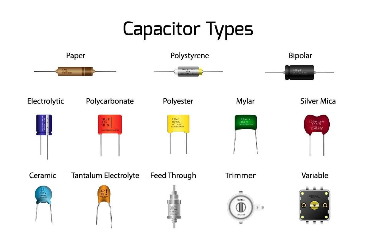
Capacitors play a pivotal role in energy storage, filtering, and decoupling within power supplies. Power supply PCB capacitor types must address bulk storage for low-frequency ripple and high-frequency bypassing for noise suppression. Electrolytic capacitors offer high capacitance density for input and output stages but suffer from limited lifespan due to electrolyte drying. Ceramic capacitors excel in decoupling applications with low ESR and high reliability across temperatures. Tantalum and film types provide intermediate options for specific voltage and stability needs. Selection hinges on calculating required capacitance from formulas like C = I * t / ΔV, where ripple voltage tolerance guides the value.
Resistors in power supplies handle tasks from current sensing to feedback loops and snubbers. Power supply PCB resistor values demand precision calculations based on circuit equations, such as voltage divider ratios for regulation control. Low-value shunt resistors for current sensing require tight tolerances, often 1% or better, to minimize measurement errors. Power rating must exceed dissipation by a safety factor, typically calculated as P = I2R under peak conditions. Temperature coefficient of resistance affects long-term accuracy in hot environments. Surface-mount thick-film or wirewound types suit most applications, balancing size and thermal performance.
Diodes manage rectification, freewheeling, and protection duties in power circuits. Power supply PCB diode selection focuses on forward voltage drop, reverse recovery time, and surge current capability. Schottky diodes minimize conduction losses in low-voltage outputs with their low Vf, ideal for point-of-load converters. Standard silicon diodes suffice for high-voltage rectification but exhibit slower recovery, generating switching losses. Fast-recovery diodes bridge the gap for medium-frequency switchers. Ratings should exceed peak inverse voltage by at least 50% and average forward current by operational margins.
Beyond these primaries, inductors and semiconductors round out the selection. Inductors store magnetic energy, requiring core materials like ferrite for high-frequency operation and sufficient saturation current. MOSFETs or IGBTs for switching demand low on-resistance and gate charge optimization. Integrated controllers simplify designs but necessitate matching passives. Layout considerations, such as minimizing loop areas, interact with component parasitics to control EMI. IPC-2221 provides generic guidelines for these interactions in PCB design.
Practical Best Practices for Power Supply PCB Components Selection
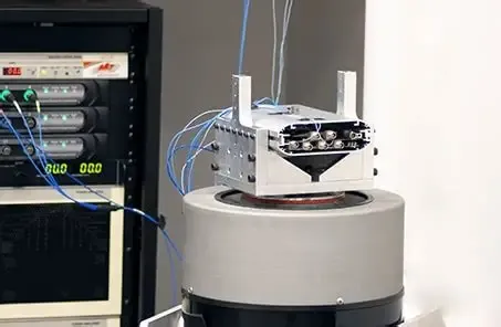
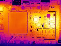
Start with a detailed schematic review and simulation to predict stresses before procurement. Apply derating rules: capacitors at 50-70% voltage rating, resistors at 50% power, diodes at 80% current. Source components from qualified suppliers with traceability to JEDEC standards for reliability testing. Prototype testing validates choices under accelerated conditions like temperature cycling and vibration. Power supply PCB components selection improves with iterative feedback from thermal imaging and oscilloscope measurements.
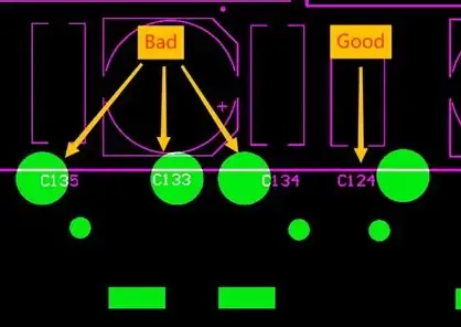
For capacitors, prioritize low-ESR types in high-ripple positions and stack multiple for redundancy. In multi-layer ceramics, account for DC bias derating where capacitance halves at rated voltage. Electrolytics benefit from series-parallel configurations to share stress. Power supply PCB capacitor types selection also considers mounting orientation to avoid mechanical stress in vibration-prone setups.
Resistor placement near heat sources requires higher wattage or arrays for dissipation. Use 0.1% tolerance for precision feedback to enhance loop stability. Fuse resistors add protection without discrete components. Calculating power supply PCB resistor values involves worst-case analysis, including ambient temperature rises.
Diode arrays or TVS for protection clamp transients effectively. Select based on power supply topology: ultrafast for PFC stages. Thermal vias under packages aid heat sinking. Power supply PCB diode selection ensures soft-recovery traits to reduce EMI spikes.
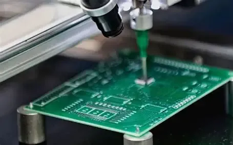
Incorporate passive networks for stability, like RC snubbers across switches. Ferrite beads suppress conducted noise. Component footprints follow IPC-7351 land pattern standards for solderability. Final assembly per J-STD-001 ensures joint integrity under thermal cycling.
Common Troubleshooting Insights
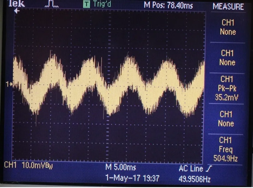
Overheating often traces to underrated passives; measure junction temperatures empirically. Excessive ripple signals capacitor aging or insufficient value; swap types systematically. Oscilloscope probing reveals diode recovery artifacts as voltage overshoots. Feedback instability from resistor drift demands recalibration. Layout-induced parasitics mimic component faults; review ground planes. These diagnostics refine future power supply PCB components selection.
Conclusion
Mastering power supply PCB components selection demands a holistic approach integrating topology needs, stress analysis, and best practices. Capacitor types, resistor values, and diode choices directly dictate efficiency and reliability. Engineers benefit from derating, simulation, and standards adherence for robust outcomes. Prioritizing these elements minimizes field failures and optimizes performance. Future designs will leverage advancing materials while grounding in proven principles.
FAQs
Q1: What factors influence power supply PCB capacitor types selection?
A1: Power supply PCB capacitor types depend on application needs like bulk storage, decoupling, or filtering. Electrolytic types suit low-frequency ripple handling with high capacitance, while ceramics provide low ESR for high-speed switching. Consider voltage derating, temperature range, and lifespan under ripple current. ESR and size constraints guide final choices for optimal stability.
Q2: How do you determine power supply PCB resistor values?
A2: Power supply PCB resistor values stem from circuit functions like sensing, dividing, or damping. Use equations such as R = V/I for shunts or divider ratios for feedback. Factor in tolerance, power dissipation with margins, and temperature coefficients. Precision types ensure regulation accuracy under load variations. Validate through simulation and thermal checks.
Q3: What criteria guide power supply PCB diode selection?
A3: Power supply PCB diode selection hinges on Vf, Vrrm, If, and recovery time matching the topology. Schottky diodes favor efficiency in low-drop applications, while fast-recovery diodes suit switching stages. Surge ratings protect against inrush, and package choice should support thermal paths. Derate for peaks and test for EMI contributions.
Q4: Why is derating essential in power supply PCB components selection?
A4: Derating extends reliability by operating components below absolute maximums. Capacitors at about 50% voltage avoid dielectric stress, and resistors at roughly half power reduce thermal runaway risk. It accounts for aging, transients, and environmental variability, aligning with standards like JEDEC to improve longevity and MTBF.
References
IPC-2221B — Generic Standard on Printed Board Design. IPC, 2012
JEDEC J-STD-020E — Moisture/Reflow Sensitivity Classification of Nonhermetic Surface Mount Devices. JEDEC, 2014
J-STD-001G — Requirements for Soldered Electrical and Electronic Assemblies. IPC, 2011
IPC-6012E — Qualification and Performance Specification for Rigid Printed Boards. IPC, 2017