 ALLPCB


Introduction
Solder mask serves as a protective layer on printed circuit boards, shielding copper traces from environmental factors and preventing unintended solder connections during assembly. While green remains the most common color due to its long-standing use and compatibility with standard processes, blue solder mask has gained attention in specific manufacturing scenarios. Engineers and production teams select blue for its distinct optical properties that can support improved visual and automated inspection outcomes. This choice directly influences how teams address blue solder mask manufacturing defects and maintain consistent blue solder mask process control throughout fabrication. When applied correctly, blue variants contribute to higher blue solder mask yield and enhanced blue solder mask reliability in demanding applications.
Why Blue Solder Mask Matters in PCB Manufacturing
Blue solder mask provides greater contrast against white or light-colored silkscreen markings compared with traditional green. This contrast helps operators and inspection systems identify trace outlines, pad locations, and potential anomalies more readily during quality checks. In high-volume production environments, such visibility supports faster detection of issues that might otherwise escape notice until later assembly stages. Factory teams often turn to blue when working with complex layouts or when downstream processes require precise component placement verification. The material also aligns with certain industry preferences for boards destined for equipment where maintenance personnel perform frequent visual reviews. Overall, the selection of blue integrates into broader efforts to optimize blue solder mask yield without altering core fabrication sequences.
Technical Principles of Blue Solder Mask Application
The application of blue solder mask follows the same fundamental sequence used for other colors: surface preparation, coating, exposure through a photomask, development, and thermal curing. Pigments in the blue formulation modify how the liquid or dry-film resist absorbs and transmits ultraviolet light during the exposure step. This optical difference requires careful adjustment of exposure energy and time to achieve proper polymerization across the entire panel. Thickness uniformity remains critical because variations can lead to incomplete coverage or overly thick deposits that affect subsequent soldering behavior. Cross-sectional analysis after curing confirms that the cured film meets the mechanical and chemical resistance requirements expected in finished boards.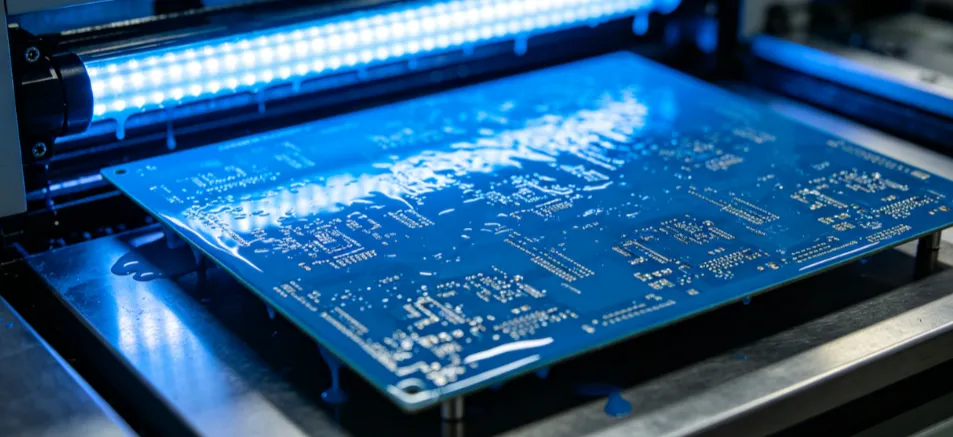
Process Control Measures That Reduce Blue Solder Mask Manufacturing Defects
Effective blue solder mask process control begins with incoming material verification and continues through each process step with documented parameters. Coating equipment must deliver consistent viscosity and film thickness, as pigment loading in blue formulations can influence flow characteristics during application. Exposure settings are calibrated specifically for the blue resist to ensure complete curing in fine-pitch areas while avoiding overexposure that could cause residue or undercut. Development chemistry and dwell times are monitored to prevent incomplete removal of uncured resist, which might create insulation issues or solder mask slivers. Thermal curing profiles are validated to achieve full cross-linking without introducing warpage or discoloration. Regular in-process inspections, including both visual and automated optical methods tuned for blue reflectance, help catch deviations early. 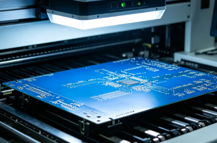
Best Practices for Improving Blue Solder Mask Yield and Reliability
Production teams achieve higher blue solder mask yield by maintaining tight control over environmental conditions in the solder mask area, such as temperature, humidity, and cleanroom classification. Panel handling procedures minimize mechanical stress that could cause micro-cracks in the cured film, particularly on thinner substrates. Design rules incorporate appropriate clearances around pads and traces to accommodate the blue resist’s typical resolution limits. Post-cure inspection criteria follow established acceptability guidelines that evaluate coverage, registration, and surface quality. When boards undergo thermal cycling or reflow, the cured blue solder mask must demonstrate stable adhesion and resistance to cracking or delamination. These practices collectively support long-term blue solder mask reliability in end-use environments. 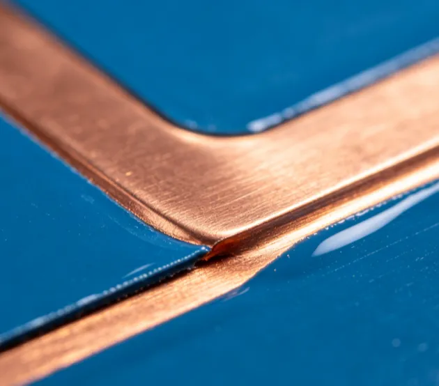
Conclusion
Blue solder mask offers practical advantages in inspection visibility and process monitoring that can complement standard green options in appropriate applications. By focusing on material-specific process controls and adherence to recognized industry specifications, manufacturers reduce the incidence of blue solder mask manufacturing defects while sustaining high blue solder mask yield. Consistent attention to these factors also strengthens overall blue solder mask reliability across production lots. Engineers who evaluate color selection as part of a holistic quality strategy often find that blue contributes to smoother factory operations and fewer downstream issues.
FAQs
Q1: How does blue solder mask affect manufacturing defects compared with other colors?
A1: Blue solder mask manufacturing defects are primarily influenced by exposure and development parameters rather than the color itself. Proper calibration of ultraviolet energy and development chemistry minimizes common issues such as incomplete curing or residue. Teams that implement color-specific inspection recipes typically observe comparable or lower defect rates when process controls remain stable.
Q2: What process control steps are most important for blue solder mask?
A2: Blue solder mask process control centers on verifying coating thickness, optimizing exposure settings for the pigment’s light absorption, and confirming full development and cure. Monitoring these variables at each stage prevents variations that could reduce yield or compromise coverage on fine features.
Q3: Can blue solder mask improve overall yield in PCB production?
A3: Blue solder mask yield benefits from enhanced contrast during automated and manual inspection, allowing earlier detection of registration or coverage problems. When combined with disciplined process monitoring, this visibility supports higher first-pass yields without requiring major equipment changes.
Q4: How does blue solder mask contribute to long-term reliability?
A4: Blue solder mask reliability depends on achieving uniform thickness, complete cure, and strong adhesion to the underlying copper and laminate. Boards processed under controlled conditions demonstrate stable performance through thermal and environmental stresses when they meet the same qualification criteria applied to other solder mask colors.
References
IPC-A-600K — Acceptability of Printed Boards. IPC, 2020
IPC-6012E — Qualification and Performance Specification for Rigid Printed Boards. IPC, 2017
IPC-SM-840E — Qualification and Performance Specification of Permanent Solder Mask and Flexible Cover Materials. IPC, 2010





