 ALLPCB


Why a Glossy Solder Mask Finish Matters in PCB Manufacturing
Solder mask serves as a critical protective coating on printed circuit boards, shielding copper traces from oxidation, moisture, and mechanical damage while providing electrical insulation between conductors. Achieving a flawless glossy finish enhances both functional performance and visual quality, which supports easier visual inspection during manufacturing and assembly. In modern PCB production, the appearance of the solder mask often reflects overall process control and adherence to quality standards. Engineers and manufacturers prioritize glossy finishes because they reduce light scattering that can obscure defects and improve the perceived reliability of the final product.
Technical Principles Behind Gloss Formation
The gloss of a solder mask depends on the polymerization behavior of the resin system during ultraviolet exposure and thermal curing. Liquid photoimageable solder masks, commonly used in advanced manufacturing, contain photoinitiators that trigger cross-linking when exposed to specific wavelengths of light. Uneven exposure energy or inconsistent film thickness can produce surface irregularities such as orange peel texture or micro-bubbles that scatter light and reduce gloss. Surface preparation of the copper prior to mask application also plays a decisive role, because residual oxides or organic contaminants interfere with wetting and create localized dull spots. Controlled cleanroom conditions limit airborne particles that might embed in the wet film and disrupt the final surface topography.
Curing parameters further determine the degree of surface smoothness. Insufficient thermal post-cure can leave the mask under-polymerized, resulting in a softer, less reflective surface. Conversely, excessive heat or prolonged exposure may cause yellowing or cracking that compromises both appearance and long-term reliability. Thickness uniformity, typically maintained within tight tolerances, ensures that the top surface cures evenly and achieves maximum specular reflection. These mechanisms are evaluated during process qualification to confirm that production boards satisfy acceptance criteria for both visual and functional performance.
Practical Solutions and Best Practices for Flawless Results
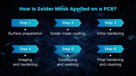
Manufacturers achieve consistent glossy finishes through rigorous surface preparation sequences that include chemical cleaning, micro-etching, and thorough rinsing. Maintaining low humidity and stable temperature in the application area prevents moisture absorption that can cause haze or fisheyes in the cured mask. Application methods such as curtain coating or precision spraying allow finer control over wet film thickness than traditional screen printing, reducing the likelihood of thickness variations that affect gloss. After imaging and development, a carefully optimized thermal cure cycle completes the cross-linking reaction and locks in the smooth surface morphology.
Process monitoring at each stage supports reproducibility. Inline thickness measurement and gloss metering provide immediate feedback, enabling adjustments before defects propagate through the line. Environmental controls, including filtered air and static elimination, minimize particle contamination that would otherwise create visible imperfections. When these practices align with documented qualification procedures, the resulting solder mask exhibits uniform high gloss across complex board geometries, including fine-pitch areas and large copper planes.

Troubleshooting Common Gloss-Related Issues
Dull or uneven solder mask finishes frequently trace back to inadequate surface cleanliness or deviations in exposure dose. Contamination from handling or previous process steps can create localized areas of poor adhesion that appear matte after curing. Adjusting the pre-treatment chemistry or extending rinse times often restores the desired gloss level without altering other parameters. In cases where gloss varies across a panel, engineers examine the coating equipment for nozzle wear or inconsistent pump pressure that produces thickness gradients.
Another frequent cause involves curing profile mismatches. Boards that exit the oven with insufficient peak temperature may display a soft, low-gloss surface that improves only after an additional bake cycle. Conversely, rapid temperature ramps can trap solvents and produce a hazy appearance. Systematic logging of oven profiles and correlation with gloss measurements help identify the optimal thermal window for each solder mask chemistry. Addressing these issues at the source maintains both visual quality and compliance with acceptance standards.

Conclusion
Consistent achievement of a flawless glossy solder mask finish requires integrated control of surface preparation, application parameters, exposure settings, and curing conditions. When these elements operate within established process windows, the resulting coating delivers both enhanced protection and improved visual characteristics valued by inspection teams and end users. Manufacturers that embed these techniques into daily operations reduce rework and support higher first-pass yields across diverse PCB designs.
FAQs
Q1: What solder mask techniques most influence the final glossy appearance?
A1: Surface cleanliness, precise wet film thickness control, and optimized ultraviolet exposure combined with thermal curing determine gloss levels. Consistent execution of these steps across production lots produces uniform specular reflection and minimizes surface defects that scatter light.
Q2: How does solder mask finish quality affect PCB manufacturing outcomes?
A2: A flawless glossy finish improves visual inspection accuracy and reduces the chance of contaminants adhering to the surface. It also supports better long-term reliability by indicating proper polymerization and adhesion throughout the coating.
Q3: Which process controls help maintain a flawless finish during high-volume production?
A3: Cleanroom environmental management, real-time thickness and gloss monitoring, and validated curing profiles ensure repeatability. These controls limit variation and help every panel meet the same surface quality targets.
Q4: Why do some boards show dull patches after solder mask curing?
A4: Dull patches usually result from localized contamination, thickness inconsistencies, or curing profile deviations. Corrective actions focus on improving pre-treatment, equipment calibration, or thermal process settings to restore uniform gloss.





