ALLPCB


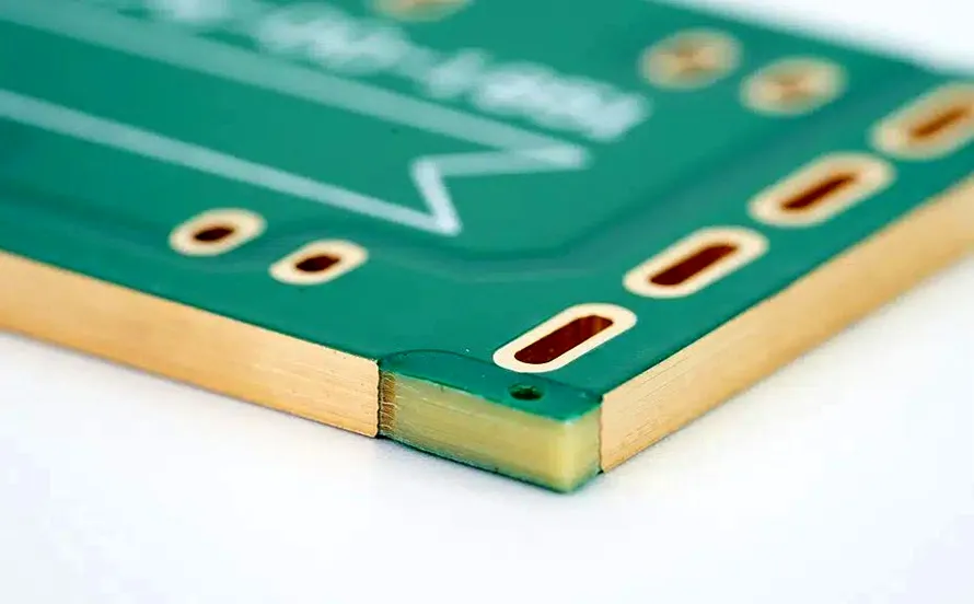
When it comes to designing a printed circuit board (PCB), one of the most important decisions you'll make is selecting the right thickness. PCB thickness impacts everything from mechanical strength to electrical performance and thermal management. Whether you're a beginner or a seasoned engineer, understanding PCB thickness standards and how to choose the best option for your project is crucial. In this comprehensive guide, we'll break down everything you need to know about PCB thickness selection, including a detailed PCB thickness chart, standards, and practical tips to help you make an informed decision for your next project.
Why PCB Thickness Matters in Your Design
PCB thickness is more than just a physical dimension; it plays a vital role in the overall functionality and reliability of your electronic device. A board that's too thin may lack the structural integrity to withstand mechanical stress, while a board that's too thick could increase costs unnecessarily or interfere with space constraints in compact designs. The thickness of a PCB affects:
- Mechanical Durability: Thicker boards are more robust and less likely to warp or break under stress.
- Electrical Performance: Thickness influences impedance control, especially in high-frequency applications where signal integrity is critical.
- Thermal Management: Thicker boards can handle more heat dissipation, which is essential for high-power applications.
- Manufacturing Costs: Thicker boards often require more material and processing time, increasing production costs.
With these factors in mind, let's dive into the details of PCB thickness explained, starting with the standard options available and how they apply to different projects.
What Are the Standard PCB Thickness Options?
The thickness of a PCB is typically measured in millimeters (mm) or inches, and there are several industry-standard options that manufacturers commonly offer. These standards have evolved to balance performance, cost, and compatibility with common components and assembly processes. Here are the most common PCB thickness standards:
- 0.4 mm (0.016 inches): Ultra-thin boards used in very compact devices like wearables or flexible circuits.
- 0.8 mm (0.031 inches): Thin boards often found in lightweight or space-constrained applications.
- 1.0 mm (0.039 inches): A middle-ground option for designs needing a balance of durability and compactness.
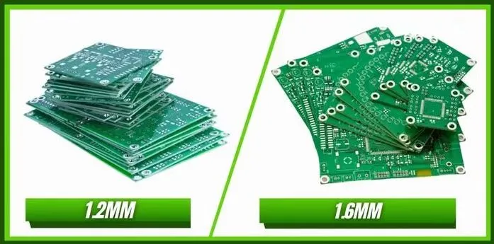
- 1.6 mm (0.063 inches): The most widely used standard thickness, suitable for most general-purpose applications due to its balance of strength and cost.
- 2.0 mm (0.079 inches): Thicker boards for applications requiring extra durability or heat dissipation.
- 2.4 mm (0.094 inches) and above: Used in high-power or industrial applications where mechanical strength and thermal performance are critical.
Among these, 1.6 mm is often considered the "go-to" thickness because it fits a wide range of components, provides good mechanical stability, and is cost-effective for manufacturing. However, the right choice depends on the specific needs of your project.
PCB Thickness Chart: A Quick Reference
To make PCB thickness selection easier, we've compiled a simple chart that outlines common thicknesses, their typical applications, and key considerations. Use this as a starting point when planning your design.
| Thickness (mm) | Thickness (inches) | Typical Applications | Key Considerations |
|---|---|---|---|
| 0.4 | 0.016 | Wearables, Flexible PCBs | Fragile, limited component compatibility |
| 0.8 | 0.031 | Compact electronics, lightweight designs | Moderate strength, space-saving |
| 1.0 | 0.039 | Consumer electronics, small devices | Balanced durability and size |
| 1.6 | 0.063 | General-purpose PCBs, most standard projects | Industry standard, widely compatible |
| 2.0 | 0.079 | Industrial equipment, power supplies | Enhanced strength and heat handling |
| 2.4+ | 0.094+ | High-power applications, heavy-duty designs | Maximum durability, higher cost |
Factors to Consider in PCB Thickness Selection
Choosing the right PCB thickness isn't just about picking a number from a chart. Several factors specific to your project will influence the best choice. Let's explore these in detail to ensure you make an informed decision.
1. Application and Environment
The environment where your PCB will operate is a major factor. For example, a PCB in a rugged industrial setting may need to be thicker (e.g., 2.0 mm or more) to handle vibrations and physical stress. On the other hand, a PCB for a small consumer gadget like a smartwatch might work best with a thinner board (e.g., 0.4 mm or 0.8 mm) to save space and weight.
2. Electrical Requirements
Electrical performance, especially in high-frequency or high-power designs, is heavily influenced by PCB thickness. Thicker boards can support wider traces and higher current capacities, which is critical for power electronics. For instance, a board handling 5A of current may require a thickness of 2.0 mm with a copper weight of 2 oz/ft2 to avoid overheating. Additionally, in high-frequency designs, the dielectric thickness (part of the overall board thickness) affects impedance. A typical 50-ohm impedance for RF signals often requires precise control of layer spacing, which might dictate a specific board thickness like 1.6 mm with a defined stack-up.
3. Component Compatibility
Some components, especially connectors and through-hole parts, are designed for specific PCB thicknesses. For example, many standard connectors are optimized for 1.6 mm boards. If your design uses non-standard thickness, you may face compatibility issues or need custom components, which can increase costs.
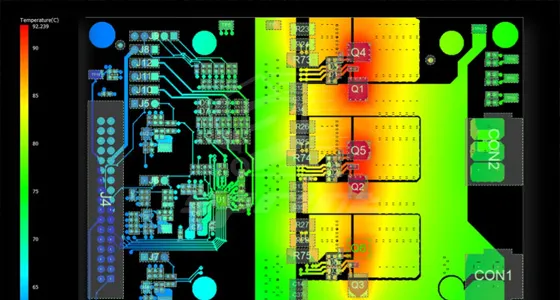
4. Thermal Management
Heat dissipation is a critical concern in high-power applications. Thicker boards can handle more heat due to their larger mass and ability to incorporate thicker copper layers. For a power supply board dissipating 10W of heat, a 2.4 mm thickness with a 3 oz/ft2 copper layer might be necessary to prevent thermal runaway.
5. Cost and Manufacturability
Thicker boards generally cost more due to the increased material and processing time. If your project doesn't require extra thickness for performance reasons, sticking to a standard like 1.6 mm can save money. Additionally, non-standard thicknesses may not be supported by all manufacturing processes, leading to longer lead times or higher costs.
How PCB Thickness Affects Layer Stack-Up
In multilayer PCBs, thickness is not just about the overall board but also about the arrangement of layers and the dielectric material between them. The stack-up—the way layers of copper and insulating material are arranged—plays a big role in electrical performance, especially for impedance control and signal integrity.
For example, in a 4 layer PCB with a total thickness of 1.6 mm, the dielectric spacing between layers might be around 0.2 mm to 0.3 mm to achieve a controlled impedance of 50 ohms for high-speed signals. If you change the overall thickness to 2.0 mm without adjusting the stack-up, the impedance could shift, affecting signal performance. This is why PCB thickness selection must consider not just the total value but also how it's distributed across layers.
Special Cases: Thin and Flexible PCBs
While standard rigid PCBs dominate most applications, thin and flexible PCBs are increasingly popular in modern electronics. Thin PCBs (below 0.8 mm) and flexible circuits often use materials like polyimide and can be as thin as 0.1 mm. These are ideal for compact or bendable designs, such as in medical devices or foldable smartphones. However, their reduced thickness comes with trade-offs, including lower mechanical strength and challenges in mounting heavy components.
For flexible PCBs, thickness selection often focuses on balancing flexibility with durability. A 0.2 mm flexible board might be perfect for a wearable device but could tear under stress if not designed carefully.
Practical Tips for Choosing the Right PCB Thickness
Now that we’ve covered the basics of PCB thickness explained, here are some actionable tips to guide your selection process:
- Start with the Standard: If you’re unsure, begin with a 1.6 mm thickness. It’s widely supported, cost-effective, and compatible with most components.
- Match Your Application: Consider the physical and electrical demands of your project. High-power or industrial designs often need thicker boards, while compact devices benefit from thinner ones.
- Consult Your Manufacturer: Early in the design phase, check with your PCB supplier to confirm available thicknesses and any cost implications for non-standard options.
- Simulate Electrical Performance: Use PCB design software to model impedance and signal integrity based on your chosen thickness and stack-up, especially for high-speed designs.
- Plan for Assembly: Ensure your chosen thickness aligns with the assembly process, including soldering techniques and component mounting requirements.
Conclusion: Make an Informed Choice for Your PCB Project
Selecting the right PCB thickness is a critical step in ensuring the success of your electronic project. By understanding PCB thickness standards, consulting a PCB thickness chart, and considering factors like application, electrical needs, and cost, you can make a decision that optimizes performance and reliability. Whether you're designing a simple single-layer board or a complex multilayer PCB, the right thickness will provide the foundation for a durable and efficient product.
At ALLPCB, we're committed to supporting your design journey with high-quality manufacturing solutions tailored to your needs. Use this PCB thickness guide as a resource to navigate your options and build better boards for your next innovation.