 ALLPCB


If you're dealing with issues like FR-4 PCB short circuit, open circuit FR-4, FR-4 PCB delamination, warping, or contamination, you're not alone. These common problems can disrupt your projects, but they’re often fixable with the right approach. In this practical guide, we'll walk you through identifying, troubleshooting, and resolving these issues step by step. Whether you’re looking into FR-4 PCB repair or rework, we’ve got actionable solutions to help you get back on track.
What is FR-4 PCB and Why Does it Matter?
FR-4 is a widely used material in printed circuit board (PCB) manufacturing, known for its balance of affordability, durability, and performance. It’s a glass fiber-reinforced epoxy laminate that provides excellent electrical insulation and mechanical strength. The “FR” stands for flame retardant, making it a safe choice for many applications, while the “4” indicates its specific grade within this category. FR-4 PCBs are found in everything from consumer electronics to industrial equipment, thanks to their versatility.
However, even with its robust properties, FR-4 PCBs can face problems during design, manufacturing, or operation. Issues like short circuits, open circuits, delamination, warping, and contamination can compromise performance. Understanding these challenges and knowing how to address them is crucial for engineers and hobbyists alike.
Common FR-4 PCB Problems and Their Causes
Before diving into troubleshooting, let’s break down the most frequent issues with FR-4 PCBs and what typically causes them. Recognizing the root cause is the first step to effective repair or rework.
1. FR-4 PCB Short Circuit
A short circuit happens when two conductive paths unintentionally connect, often leading to excessive current flow and potential damage. On an FR-4 PCB, short circuits can occur due to:
- Solder bridges between closely spaced pads or traces during assembly.
- Damaged insulation between layers, exposing copper traces.
- Manufacturing defects like over-etching or poor trace spacing, sometimes as small as 0.1 mm, which violates typical design rules for 5V circuits.
Short circuits can cause overheating, component failure, or even fire hazards if not addressed promptly.
2. Open Circuit FR-4
An open circuit is the opposite of a short—it’s a break in the conductive path, preventing current from flowing. Common causes include:
- Cracked traces due to mechanical stress or poor handling.
- Corrosion of copper traces, especially in humid environments.
- Incomplete soldering or lifted pads during assembly.
This issue often results in a non-functional circuit, making it critical to locate and fix the break.
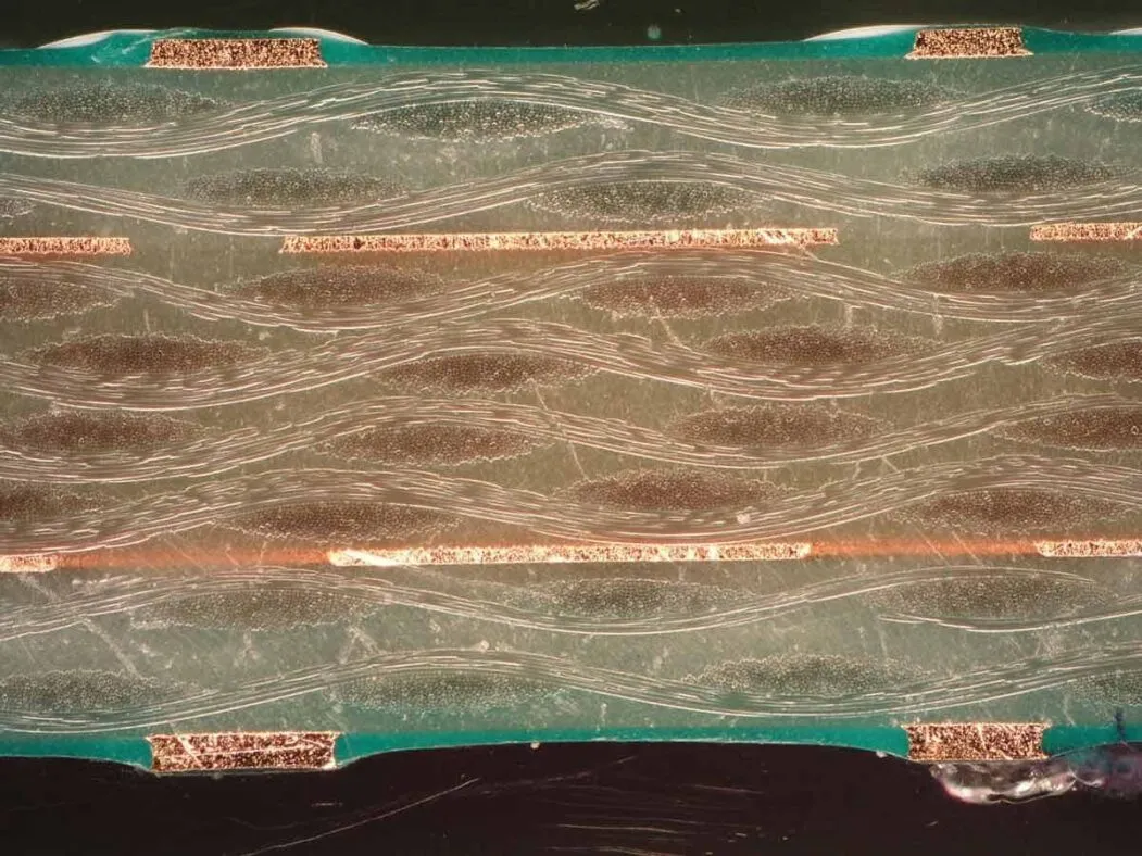
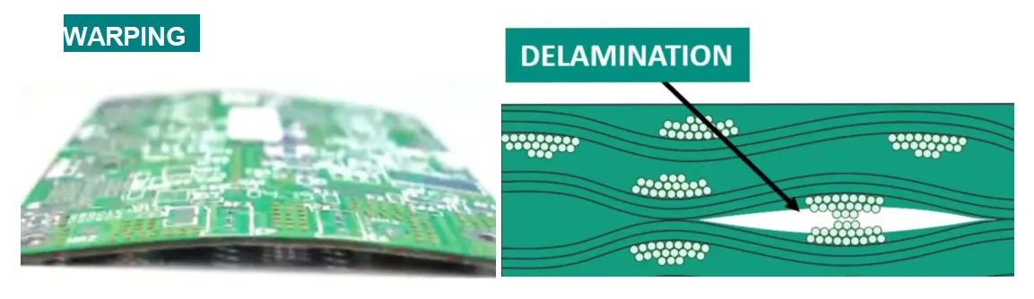
3. FR-4 PCB Delamination
Delamination refers to the separation of layers in the FR-4 material, weakening the board’s structure. It can happen because of:
- Excessive heat during soldering or reflow, often exceeding 260°C, which impacts the epoxy resin’s bonding.
- Moisture absorption, leading to internal stress and layer separation.
- Poor manufacturing processes, such as inadequate lamination pressure.
Delamination can compromise both mechanical strength and electrical performance, sometimes causing intermittent failures.
4. FR-4 PCB Warping
Warping is when the PCB bends or twists out of shape, often making assembly difficult. Causes include:
- Uneven heating or cooling during manufacturing or reflow processes, creating thermal stress.
- Improper storage in humid conditions, leading to uneven moisture absorption.
- Unbalanced copper distribution across layers, causing mechanical stress.
A warped board can lead to misaligned components and poor soldering results, affecting reliability.
5. FR-4 PCB Contamination
Contamination involves unwanted substances like dust, flux residue, or chemicals on the PCB surface. It’s often caused by:
- Inadequate cleaning after soldering, leaving flux residue that can corrode traces over time.
- Exposure to environmental pollutants during storage or use.
- Handling without proper precautions, transferring oils or dirt from hands.
Contamination can lead to signal interference, corrosion, or even short circuits if conductive residues are present.
Troubleshooting FR-4 PCB Problems: Step-by-Step Solutions
Now that we’ve identified the common issues, let’s explore practical ways to troubleshoot and resolve them. These steps are designed to be actionable, even if you’re not an expert in PCB repair.
Diagnosing FR-4 PCB Short Circuit
To find and fix a short circuit:
- Visual Inspection: Use a magnifying glass or microscope to check for solder bridges or damaged traces. Look for areas where copper lines, often spaced as close as 0.2 mm, might be touching.
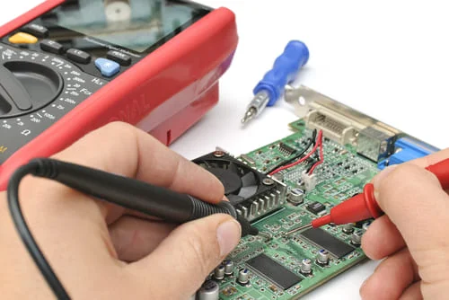
- Multimeter Test: Set your multimeter to continuity mode and test between suspected points. A beep indicates a short.
- Repair: Remove excess solder with a desoldering wick or carefully cut away unintended connections using a precision knife. Ensure proper insulation with conformal coating if needed.
Fixing Open Circuit FR-4 Issues
For an open circuit, follow these steps:
- Visual Check: Inspect the board for visible cracks or lifted pads under good lighting.
- Continuity Test: Use a multimeter to check for breaks along traces. Test points along the path until you find the disconnection.
- Repair: Bridge small breaks with conductive epoxy or a thin wire soldered across the gap. For larger damage, consider replacing the affected section with a jumper wire.
Addressing FR-4 PCB Delamination
Delamination can be tricky, but here’s how to handle it:
- Assess Damage: Determine if the delamination affects critical areas like vias or traces. Minor edge delamination may not require immediate action.
- Control Environment: Store the board in a dry, temperature-controlled area to prevent further separation. Ideal storage is at 25°C with less than 50% humidity.
- Repair: For small areas, apply epoxy resin to re-bond layers. For severe cases, replacing the board might be more cost-effective.
Correcting FR-4 PCB Warping
To fix or prevent warping:
- Check Design: Ensure balanced copper distribution in your PCB layout. Uneven copper can create stress during thermal cycles.
- Thermal Management: During reflow, use a gradual heating and cooling profile to minimize stress. Avoid sudden temperature changes above 150°C per minute.
- Physical Correction: For minor warping, apply gentle pressure with a flat weight while reheating the board to around 100°C. Be cautious to avoid further damage.
Managing FR-4 PCB Contamination
Cleaning contamination is often straightforward:
- Identify Residue: Look for sticky flux, dust, or discoloration on the board surface.
- Clean: Use isopropyl alcohol (at least 90% purity) and a soft brush to gently scrub the affected area. For stubborn residues, an ultrasonic cleaner can be effective.
- Dry Thoroughly: Ensure the board is completely dry using compressed air or a low-heat oven at 50°C for 30 minutes to prevent moisture-related issues.
Advanced FR-4 PCB Repair and Rework Techniques
For more complex issues, FR-4 PCB repair and rework might be necessary. These techniques require precision and the right tools, but they can save a board from being scrapped.
FR-4 PCB Repair for Damaged Traces
If traces are damaged beyond simple bridging:
- Use a conductive pen to redraw small sections of traces. These pens deposit silver or copper ink with a resistance as low as 0.05 ohms per square inch.
- For larger repairs, solder a thin wire (like 30 AWG) along the original trace path, securing it with adhesive for stability.
FR-4 PCB Rework for Component Replacement
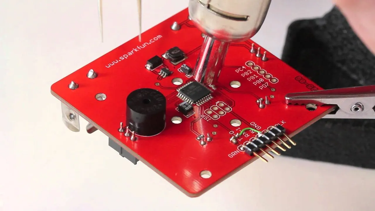
Reworking a board often involves replacing faulty components:
- Use a hot air rework station to desolder components. Set the temperature to around 300°C for lead-free solder, and use flux to ease removal.
- Clean the pads with desoldering braid and alcohol before soldering the new component in place. Ensure alignment to avoid further stress on the board.
Preventing FR-4 PCB Problems Before They Start
While troubleshooting and repair are essential skills, prevention is always better. Here are some tips to minimize FR-4 PCB issues during design, manufacturing, and handling:
- Design for Reliability: Follow proper trace spacing (at least 0.15 mm for 3.3V circuits) and avoid placing high-heat components near sensitive areas.
- Control Manufacturing Parameters: Ensure reflow ovens maintain consistent temperatures, ideally peaking at 245°C for lead-free solder, to avoid thermal stress.
- Proper Storage: Keep boards in anti-static bags in a cool, dry environment to prevent contamination and warping.
- Handle with Care: Always wear gloves and use anti-static wrist straps to avoid transferring oils or static discharge to the board.
When to Seek Professional Help for FR-4 PCB Issues
While many FR-4 PCB problems can be fixed with the right tools and patience, some issues might be beyond a DIY approach. Consider professional assistance if:
- The board has severe delamination affecting multiple layers, requiring specialized re-lamination equipment.
- Complex multilayer designs show internal shorts or opens that are hard to trace without X-ray inspection tools.
- High-value projects are at stake, and rework risks further damage.
Conclusion: Mastering FR-4 PCB Troubleshooting
Dealing with FR-4 PCB short circuit, open circuit FR-4, delamination, warping, or contamination doesn’t have to be overwhelming. With a systematic approach to troubleshooting, the right tools like multimeters and rework stations, and a focus on prevention, you can tackle most issues effectively. Whether it’s a quick FR-4 PCB repair or a detailed rework, the key is patience and precision.
By following the practical steps outlined in this guide, you’re equipped to handle common FR-4 PCB problems and keep your projects running smoothly. Remember, every challenge is an opportunity to learn more about your craft and improve your skills in PCB design and maintenance.


