ALLPCB


Overview
The installation and commissioning of PLC control systems involve multiple sequential tasks. Each step is interdependent; mistakes can lead to commissioning failure, project delays, or equipment damage. This article summarizes practical field experience in installing and commissioning PLC control systems and discusses common installation and commissioning issues with proposed solutions.
1. System Installation and Commissioning
1.1 Preliminary technical preparation
Thorough technical preparation before installation and commissioning improves efficiency and success. Preparatory tasks include:
- Familiarize yourself with the PLC supplied technical documentation and original materials, understand performance, functions, and operational requirements, and establish operating procedures.
- Study the design documentation and system process flow, especially the control requirements for each production device. Based on this, draw subsystem process flow diagrams, interlock diagrams, system function diagrams, and system logic block diagrams to deepen understanding of system logic.
- Understand the performance, design, and installation status of each process device, particularly control and power wiring diagrams, and compare them with the physical equipment to detect and correct errors.
- On the basis of understanding the design and PLC technical documentation, list PLC I/O point tables (including internal coils list, I/O locations, corresponding devices, and functions of each I/O point).
- Study the provided program. For logically complex input and output portions, draw timing diagrams; some logical errors in the design can be identified during this step.
- Prepare commissioning plans for subsystems, then integrate them into a full system commissioning plan after group review.
1.2 PLC acceptance inspection
Acceptance inspection should be conducted jointly by the purchaser and supplier. Confirm models, quantities, and specifications of equipment, spare parts, technical documentation, and accessories, and check whether performance is intact; final verification is performed during laboratory and on-site commissioning. Both parties should sign an exchanged checklist for the inspection results.
1.3 Laboratory commissioning
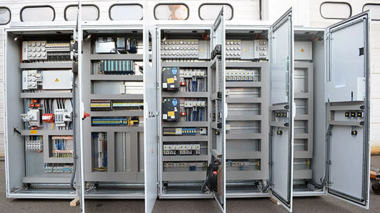
(1) Laboratory installation and power-up: fabricate metal mounting racks and secure the input/output modules of each workstation. Connect each station to the host, programmer, and printer using appropriate coaxial cables according to installation guidelines. Verify wiring correctness and that supply voltage matches PLC voltage selection. Follow power-up procedures, install system configuration media, confirm system configuration, load programming media, and power up the system according to operating procedures. Functional tests can begin at this point.
(2) Enter the working program into the PLC.
(3) Simulate I/O inputs and outputs to verify and adjust the program. This step validates the correctness of the entered program and whether the logic correctly implements the required interlocks and process control. If the program does not run through the entire process, it must be corrected. Understanding of the program will deepen during this phase, preparing for on-site commissioning and revealing parts of the program that are unreasonable or incomplete for further optimization.
There are two commissioning methods:
- Simulation method: build a physical test panel that uses push-button switches to simulate input nodes and small relays to simulate field device relays and contactors; auxiliary contacts simulate feedback signals. Advantage: realistic simulation, can reveal logic misoperations due to different speed characteristics between mechanical field contacts and PLC electronic contacts. Disadvantage: increased cost and more work.
- Force method: use PLC force functions to set mechanical field contacts in the program to forced ON/OFF to force program execution. Advantage: less work and simpler, no extra cost. Disadvantage: logic verification is incomplete; forced inputs may prevent continuous program execution, requiring segmented testing.
Based on field experience, simulate critical field nodes and use force for the remainder to combine strengths. During logic verification, maintain a daily commissioning log covering personnel, time, commissioning content, modification records, faults and resolutions, and acceptance signatures to establish responsibility and preserve primary commissioning records. Mark any program modifications on design drawings and consult the designer to ensure accurate reflection of design intent.
1.4 On-site PLC installation and inspection
After laboratory commissioning, move equipment to the site for installation when conditions permit. During installation, ensure modules are firmly seated and bolted. Use uniform communication cable types and do not mix models. If necessary, measure signal attenuation with instruments; attenuation must not exceed design specifications. Measure insulation resistance to ground for the host, I/O cabinets, and connecting cables; measure grounding resistance for the system ground; check supply power and document results. Only power up when all items meet requirements.
1.5 Field device wiring, I/O point and signal verification
Check and confirm correctness of control and main power wiring of field process equipment, and perform single-unit no-load tests in manual mode. Verify all PLC input points (including selector switches, pushbuttons, relay and contactor contacts, limit switches, and instrument calibration or selector switches) and their wiring to PLC input modules by repeated operation.
Verify all relays, contactor coils, and other actuators driven by PLC outputs and their wiring to output modules. Measure and record circuit resistance and insulation resistance to ground. If necessary, power the output circuits at the appropriate supply voltage to ensure no shorts exist; otherwise, applying power may damage modules.
For medium and large PLCs with analog I/O modules, verify primary sensors or transmitters for analog inputs and the actuators receiving analog outputs. Inject representative analog signals into transmitters and check that the transmitted analog values meet PLC input standards. Inject equivalent analog signals to actuators to confirm correct operation. PLCs with analog I/O can monitor process parameters, compute according to configured models, and perform process control.
This step is critical. The verification and adjustment process is complex and must be treated seriously. If all external devices are sound, external nodes supplied to the PLC are correct and stable, wiring is correct, and program logic is validated, then the subsequent integrated commissioning can succeed with high efficiency.
1.6 System dry-run simulation
The purpose is to place the lab-tested PLC and logic into the actual process flow and validate system logic through the field device I/O nodes and wiring.
For testing, open two phases of the main power circuits of PLC-controlled process devices (leaving one phase to power relay control circuits) to prevent rotation during power-up. Perform system simulation tests for different operating modes and control functions according to design. First confirm the correct positions of selector switches and mode selection switches, then start the system via the PLC and observe and record outputs: relay and contactor energization and de-energization, sequence, timing intervals, and signal indicators to verify compliance with design logic. Record other device behaviors.
For actuators that do not operate during the dry-run, simulate their signals by manual assistance, external inputs, or internal forcing as appropriate to allow the PLC to command the system according to the design logic.
1.7 Single-unit commissioning under PLC control
This step confirms whether PLC output circuits can drive relays and contactors to start equipment and whether the equipment returns correct feedback signals to PLC inputs and limit switches act properly.
Method: use PLC force to activate the output nodes corresponding to a specific device (motor, actuator, etc.) so its relay or contactor operates and the device runs. Observe and record the device operation, and verify feedback signals and limit switch or actuator behavior.
Exercise particular caution: any forced-start device must display danger signage and be attended by dedicated personnel. The PLC operator may only force-start after permission from the local attendant. Do not force-start equipment without adequate preparation to ensure safety.
1.8 System no-load integrated commissioning under PLC control
The goal is to confirm that individually tested devices and a logically validated PLC program, when connected, operate correctly under process requirements, and that the signal system is reliable and stable. Prepare a system no-load integrated commissioning plan and execute it after group review.
Start with subsystem integration using manual assistance for subsystem interlocks (node shorting or forcing), then proceed to full-system integration. Test all designed start/stop and operating modes, emergency and fault stops, and various signals. Simulate fault states using forced inputs as required. Fully anticipate scenarios to align tests with actual site conditions.
Before integrated load commissioning, perform a comprehensive system check and train operators to ensure first-time success of the load commissioning.
2. Signal Attenuation Considerations
- The maximum allowable signal attenuation from the PLC host to an I/O station is 35 dB. Plan cable routing carefully to minimize length (signal attenuation increases approximately 0.8 dB per 1 km). Minimize use of splitters (each splitter attenuates about 14 dB) and cable joints (each joint about 1 dB).
- Use a single-bus topology for communication cables: a common communication trunk with splitters to I/O stations rather than a star topology. Keep the number of I/O stations and distances balanced on both sides of the PLC host to achieve better impedance matching.
- Locate splitters as close to I/O stations as possible to reduce interference.
- Terminate communication cable ends with 75 Ω BNC terminators connected to I/O cabinets. When disconnecting a cable from an I/O cabinet, leave a 75 Ω terminator on the cable end to maintain proper matching.
- Maintain a minimum separation between communication cables and high-voltage power cables of 40 cm per kV. If crossing is unavoidable, cross at right angles.
- Avoid running communication cables parallel to AC power lines to reduce interference. Also avoid routing near large motors, welding equipment, or large inductive loads.
- Avoid laying communication cables in high-temperature or chemically corrosive areas.
- Allow 0.05%/°C slack in cable routing to accommodate thermal expansion and contraction.
- Tightly secure all cable joints and splitters with screws.
- When stripping cable sheaths, avoid damaging the shield; when cutting the metal braid from the insulation, use proper wire-stripping tools and do not nick the center conductor.
3. System Grounding Considerations
- Ground the host and branch stations using 10 mm2 braided copper conductors tied together and routed via a dedicated down conductor to an independent grounding grid. This must be separate from the low-voltage grounding grid to avoid interference. System ground resistance should be less than 4 Ω. Insulate the PLC host, panels, and cabinets from the foundation with a 3 mm rubber pad and insulate bolts as required.
- Ground the I/O station enclosures using individual down conductors to the common grounding grid.
- Connect the communication cable shield together at the PLC host side I/O processing modules to the dedicated system grounding grid; do not ground the shield at the I/O station side. Cable connector grounding should be via the shield to the dedicated grid. Never create a closed loop by grounding the shield at two points, as this can cause interference.
- Use isolated power supplies where the neutral is floating; when unbalanced currents occur, they will return to the supply neutral rather than via protective earth, avoiding ground loop interference with PLC operation.
- Connect the I/O module ground to the power supply neutral.
4. Commissioning Precautions
- Before bringing the system online, perform configuration to determine total I/O points, input registers, holding registers, communication ports and parameters, I/O station mapping and scheduling method, and user memory allocation. Once configured, the system operates under those constraints. Reconfiguring invalidates programs built against the original configuration and can corrupt the system. Configure carefully the first time and allow reasonable capacity for near-term expansion. However, excessive allocation increases memory usage and scan time and can reduce runtime performance. Never reconfigure a running system.
- For medium and large PLCs, the CPU scans the program in segments and updates I/O states after each segment, which improves real-time performance. Improper program segmentation can degrade real-time behavior or slow execution. Aim for roughly equal-length program segments to optimize scan times.
5. Conclusion
PLC control system installation and commissioning is a structured engineering process. Methodical execution of each step is necessary for successful commissioning. The procedures summarized here are based on field validation and have been applied in multiple technical upgrade projects to shorten schedules and improve first-time commissioning success.