 ALLPCB


PCB Trace Repair for Surface Mount Components: Tips and Techniques
Surface mount technology places components directly onto the surface of a printed circuit board, creating compact and efficient designs that dominate modern electronics. When traces become damaged during assembly, handling, or operation, targeted repair restores functionality without requiring a complete board replacement. Electric engineers often encounter these issues in prototypes, field repairs, and high-reliability applications where downtime must remain minimal. Effective trace repair for SMT components demands precision, proper materials, and adherence to established industry practices to maintain electrical integrity and mechanical stability.
Why PCB Trace Repair Matters for Surface Mount Components
Fine-pitch traces on SMT boards carry signals and power in spaces measured in fractions of a millimeter, making them vulnerable to breaks from thermal cycling, mechanical stress, or improper handling. Repairing these traces prevents costly scrapping of assemblies and supports sustainability goals by extending the life of existing hardware. In high-volume production environments, quick and reliable trace restoration keeps lines moving and reduces inventory waste. Engineers recognize that successful repairs preserve the original board layout and performance characteristics while avoiding new failure modes.
Technical Principles Behind Trace Damage in SMT Assemblies
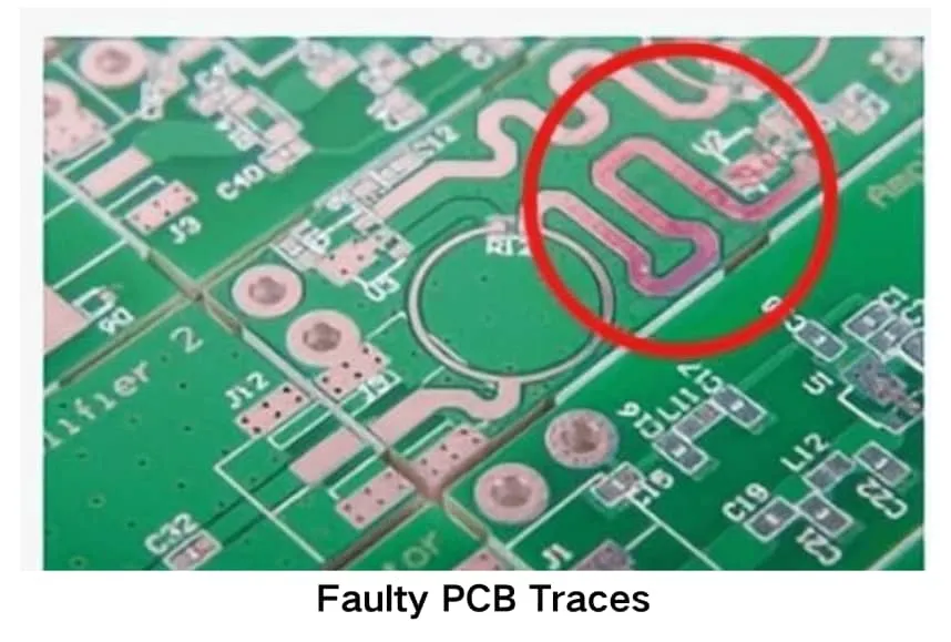
Traces on surface mount boards consist of thin copper layers bonded to the substrate, and damage often originates from excessive heat during reflow, vibration in service, or accidental scratches during rework. When a trace fractures, current flow interrupts, leading to open circuits that manifest as intermittent faults or complete device failure. Thermal expansion mismatch between copper and the laminate can exacerbate micro-cracks over repeated temperature cycles. Engineers analyze these mechanisms by examining cross-sections and using continuity testing to pinpoint exact break locations before attempting restoration.
Related Reading: PCB Trace Repair for Beginners: A Hobbyist's Guide to Saving Damaged Boards
Practical Techniques for Repairing Fine-Pitch Traces
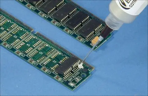
Repairing fine-pitch traces begins with thorough cleaning of the damaged area to remove oxidation and debris that would interfere with new conductive paths. Technicians typically apply a thin layer of conductive epoxy or solder a short jumper wire of appropriate gauge to bridge the gap while minimizing added inductance. For surface mount PCB repair, the chosen method must match the original trace width and thickness to maintain impedance characteristics in high-speed circuits. Careful application of flux and controlled soldering temperatures prevents lifting adjacent pads or damaging nearby components.
Best Practices in Rework Procedures
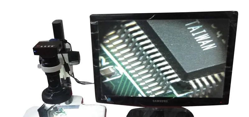
Following structured rework procedures ensures consistent results across different board types and component densities. Preparation includes masking surrounding areas to protect them from solder splatter and using magnification tools for precise alignment on fine-pitch layouts. After completing the conductive bridge, applying a protective coating restores insulation and mechanical strength comparable to the original solder mask. Verification through electrical testing and visual inspection confirms continuity and absence of shorts before returning the assembly to service.
Related Reading: The Ultimate Guide to PCB Trace Repair: Step by Step for Engineers
Troubleshooting Common Issues During SMT Trace Repair
Common challenges include poor adhesion of repair materials, which can lead to intermittent connections under thermal or mechanical load. Engineers troubleshoot by re-cleaning surfaces and selecting epoxies with appropriate resistivity and cure profiles suited to the board material. Another frequent issue arises when jumper wires introduce unwanted parasitic effects in sensitive analog or RF circuits, requiring selection of the shortest possible path and proper routing. Systematic testing at each stage helps isolate whether the repair itself introduced new problems.
Conclusion
Successful PCB trace repair for surface mount components combines careful diagnosis, appropriate materials, and methodical execution to restore full functionality. Engineers who apply these techniques extend equipment life while controlling costs and maintaining quality. Consistent application of industry-accepted methods supports reliable performance in demanding applications.
FAQs
Q1: What are the primary causes of trace damage during surface mount PCB repair?
A1: Trace damage during surface mount PCB repair typically results from excessive heat, mechanical stress, or accidental contact with tools. Engineers address these issues by following controlled procedures that limit thermal exposure and protect surrounding features. Proper preparation and inspection reduce the likelihood of new damage occurring during the repair process.
Q2: How does repairing fine-pitch traces differ from standard trace repair?
A2: Repairing fine-pitch traces requires greater precision because the narrow conductors and close spacing increase the risk of bridging or damaging adjacent elements. Techniques such as micro-soldering or selective epoxy application become essential to maintain original electrical characteristics. Engineers verify each repair with high-magnification inspection and electrical testing to confirm integrity.
Q3: What role do industry standards play in soldering SMT traces during rework?
A3: Industry standards guide the selection of materials, temperatures, and inspection criteria to ensure repaired assemblies meet original performance requirements. Procedures emphasize cleanliness, proper flux use, and post-repair verification to avoid introducing defects. Adherence to these guidelines supports consistent quality across different repair scenarios.
Q4: Can jumper wires be used effectively for surface mount trace repair?
A4: Jumper wires provide a reliable method for restoring continuity when direct trace reconstruction proves impractical on fine-pitch layouts. Engineers select wire gauge and routing paths that minimize added resistance and inductance while securing the wire against vibration. Final inspection confirms that the repair does not compromise the board's mechanical or electrical performance.
IPC-A-610 — Acceptability of Electronic Assemblies. IPC


