 ALLPCB


Why Rework Station Maintenance Matters in PCB Assembly
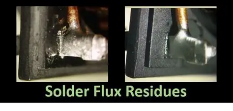
Rework stations combine hot air systems and soldering irons to handle component removal and replacement on assembled boards. In high-mix manufacturing environments, these stations see frequent use, which leads to gradual accumulation of flux residues, solder particles, and oxidation on critical surfaces. Neglected equipment can cause uneven heating or poor thermal transfer, resulting in lifted pads, damaged components, or incomplete solder joints. Consistent maintenance practices therefore protect both process yield and long-term board reliability while helping teams meet the expectations outlined in IPC-A-610 for acceptability of electronic assemblies.
Engineering Mechanisms Behind Equipment Degradation
Hot air rework systems operate by directing controlled airflow through nozzles to reflow solder joints. Over repeated cycles, flux vapors condense inside nozzles and heating elements, restricting airflow and creating temperature inconsistencies across the work area. Soldering irons experience similar issues as iron tips oxidize and develop pitting from prolonged exposure to molten solder and cleaning sponges. These physical changes alter heat delivery characteristics and increase the likelihood of thermal shock to sensitive PCB substrates or fine-pitch components. Understanding these degradation paths allows engineers to schedule interventions before performance drifts outside acceptable process windows.
Practical Maintenance Procedures for Daily Operations
Operators begin each shift by inspecting nozzles and tips for visible debris or discoloration. A soft brush and approved cleaning solution remove loose particles without scratching precision surfaces. After cleaning, stations undergo a brief functional check where airflow and temperature stability are verified against baseline readings established during initial setup. Weekly routines extend to internal filter replacement and calibration verification using traceable reference instruments. These steps ensure that rework processes remain repeatable and minimize the chance of introducing new defects during corrective actions.
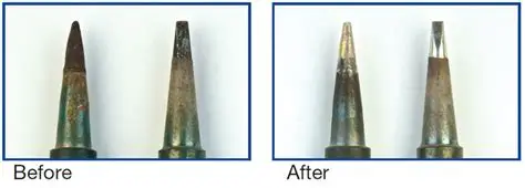
Soldering iron maintenance follows a parallel sequence. Tips receive regular tinning with fresh solder to maintain a protective coating that prevents oxidation. Worn or pitted tips are replaced promptly because they transfer heat inefficiently and increase the risk of cold joints. Iron stands and sponge holders stay clean to avoid transferring contaminants back onto the tip during normal use. Documenting these activities creates a traceable record that supports quality audits and helps identify patterns in equipment wear.
Calibration and Performance Verification Practices
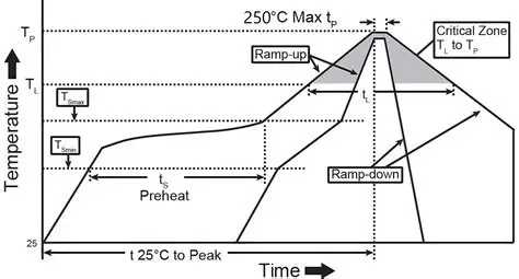
Calibration confirms that displayed temperatures and airflow rates match actual output delivered to the board. Technicians perform this verification at regular intervals using calibrated thermocouples and airflow meters placed at the work surface. Any deviation beyond established tolerances triggers adjustment or service by qualified personnel. Recalibration after major cleaning or component replacement restores accuracy and prevents cumulative drift that could affect joint quality on subsequent boards. Maintaining calibration logs also demonstrates process control during customer or regulatory reviews.
Related Reading: PCB Rework Station for Beginners: A Simple Guide to Component Replacement
Troubleshooting Common Issues in Rework Operations
When rework results show incomplete reflow or localized overheating, the first diagnostic step examines nozzle condition and airflow path. Partial blockages often manifest as uneven solder melting or prolonged cycle times. Temperature instability frequently traces back to degraded heating elements or loose connections inside the handpiece. Systematic checks of power supply output and sensor integrity isolate electrical faults before they cause board damage. Recording each troubleshooting event builds institutional knowledge that shortens future diagnostic time.
Related reading: Troubleshooting Your PCB Rework Station: Common Issues and Fixes
Best Practices for Long-Term Equipment Reliability
Storing stations in controlled environments reduces corrosion risk on internal electronics and connectors. Protective covers shield equipment from dust when not in active use. Training programs emphasize gentle handling of nozzles and tips to avoid mechanical damage that shortens service life. Spare parts inventories for high-wear items such as filters, tips, and heating elements keep downtime minimal. These habits collectively extend equipment lifespan while preserving the precision required for modern fine-pitch and lead-free assemblies.
Conclusion
Effective rework station maintenance combines routine cleaning, periodic calibration, and proactive troubleshooting to sustain consistent performance. By addressing degradation mechanisms early, engineering teams protect both product quality and process efficiency. Adherence to established industry practices ensures that corrective rework contributes positively to overall assembly reliability without introducing new variables.
FAQs
Q1: How often should pcb rework station cleaning occur during high-volume production?
A1: Daily visual inspections combined with weekly thorough cleaning remove flux residues and solder particles before they affect airflow or heat transfer. This schedule keeps equipment within operational tolerances and supports consistent joint formation on successive boards.
Q2: What does rework station calibration involve for electric engineers?
A2: Calibration compares station output readings against reference instruments at the work surface and adjusts controls as needed to restore accuracy. Regular verification prevents temperature or airflow drift that could compromise solder joint integrity during component replacement.
Q3: What are essential hot air rework station maintenance tips for preventing nozzle issues?
A3: Regular brushing of nozzles and replacement of internal filters maintain unobstructed airflow paths. Avoiding excessive flux application during rework further reduces condensation inside the system and preserves uniform heating performance.
Q4: How does soldering iron maintenance contribute to overall pcb assembly quality?
A4: Consistent tip cleaning and timely replacement ensure efficient heat transfer and prevent oxidation-related defects. Proper care of the iron reduces the likelihood of cold joints or pad damage during manual rework operations.





