 ALLPCB


Introduction
PCB rework stations play a central role in electronics manufacturing and repair operations. Engineers rely on these tools to correct assembly defects, replace components, and restore functionality without damaging surrounding circuitry. When a rework station malfunctions, production schedules slip and quality risks increase. Common problems such as insufficient heat, restricted airflow, or unexpected error codes appear frequently during daily use. Systematic rework station troubleshooting helps teams restore performance quickly and maintain consistent process control. This article examines typical failures, their root causes, and proven correction methods aligned with established industry practices.
Why Effective Rework Station Troubleshooting Matters
In high-volume PCB assembly environments, even brief equipment downtime affects throughput and yield. A hot air rework station not heating properly can leave solder joints incomplete, while low airflow prevents uniform temperature distribution across the board. These issues directly influence compliance with soldering and assembly requirements. Teams that master rework station troubleshooting reduce scrap rates and avoid repeated rework cycles. Consistent equipment performance also supports traceability and process validation demanded in regulated industries. Addressing problems early preserves both product integrity and operational efficiency.
Technical Principles Behind Common Rework Station Failures
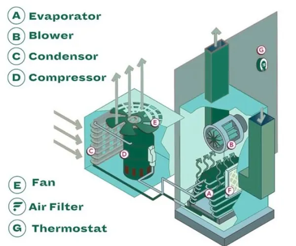
Heat generation in a rework station depends on the interaction between the heating element, temperature sensor, and control circuitry. When the element degrades or the sensor drifts, the system fails to reach or maintain the required profile. Airflow regulation involves the blower motor, ducting, and nozzle geometry; blockages or motor wear reduce velocity and create uneven heating zones. Error codes typically originate from safety interlocks or diagnostic routines that monitor current draw, temperature limits, and fan speed. These mechanisms protect the equipment and the PCB from thermal damage. Understanding these interactions allows engineers to isolate whether the fault lies in power delivery, mechanical components, or firmware interpretation.
Practical Solutions for Rework Station Troubleshooting
Begin every troubleshooting session with a visual inspection of power connections, fuses, and external filters. Verify that supply voltage matches equipment specifications before proceeding to internal checks. For a hot air rework station not heating, measure resistance across the heating element with the unit powered off; an open circuit indicates replacement is necessary. Low airflow often traces to accumulated debris in the air path or reduced fan output, so cleaning the intake and testing motor current draw restores normal operation. When error codes appear, consult the equipment manual for the specific code definition and follow the recommended sequence of power cycle, sensor recalibration, or component substitution. Always allow the station to cool completely before any internal access and document each step to support future maintenance records.
Related Reading: PCB Rework Station for Beginners: A Simple Guide to Component Replacement
Best Practices to Prevent Recurring Issues
Establish a preventive maintenance schedule that includes periodic calibration of temperature sensors against a traceable reference. Store nozzles and filters in clean environments to minimize contamination that restricts airflow. Train operators to recognize early signs such as gradual temperature overshoot or unusual fan noise before full failure occurs. Maintain spare heating elements and fan assemblies in inventory so that repairs can occur without extended production interruptions. These habits align with quality management expectations and reduce the frequency of urgent rework station troubleshooting events.
Related Reading: Boost Your PCB Repair Skills: Choosing the Right Rework Station for Your Needs
Conclusion
Reliable PCB rework depends on prompt identification and correction of equipment faults. Systematic rework station troubleshooting addresses heating failures, airflow restrictions, and error conditions before they compromise board quality. Adhering to disciplined inspection and maintenance routines keeps stations available and processes stable. Engineers who apply these methods consistently support both production goals and long-term equipment life.
FAQs
Q1: How do I begin rework station troubleshooting when the unit shows no heat?
A1: Start by confirming power supply integrity and checking the heating element continuity with a multimeter. Next, inspect the temperature sensor for proper connection and calibration. If these checks pass, review any displayed error codes for guidance on control board or fuse issues. Document findings before replacing components to maintain process traceability.
Q2: What causes low airflow in a hot air rework station and how is it fixed?
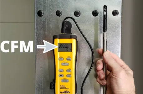
A2: Restricted airflow commonly results from clogged filters, debris in the nozzle, or reduced fan performance. Clean or replace the filter and clear the air path first. Measure output velocity at the nozzle to confirm restoration. Persistent low flow may require fan motor inspection or replacement.
Q3: How should error codes be interpreted during PCB rework station repair?
A3: Error codes indicate specific safety or performance limits exceeded by the system. Refer to the manufacturer documentation for the exact meaning of each code. Follow the prescribed reset or diagnostic sequence, then verify operation under controlled conditions. Persistent codes after reset usually point to sensor or control circuit faults requiring further component-level checks.
Q4: What routine checks prevent common rework station problems?
A4: Perform visual inspections of connections and filters before each shift. Verify temperature accuracy with a calibrated probe at regular intervals. Clean airflow paths and test fan operation weekly. Keep maintenance logs to identify patterns and schedule component replacements proactively.


