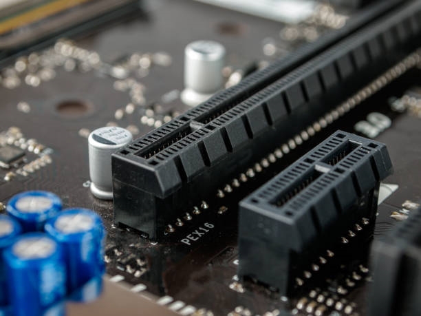
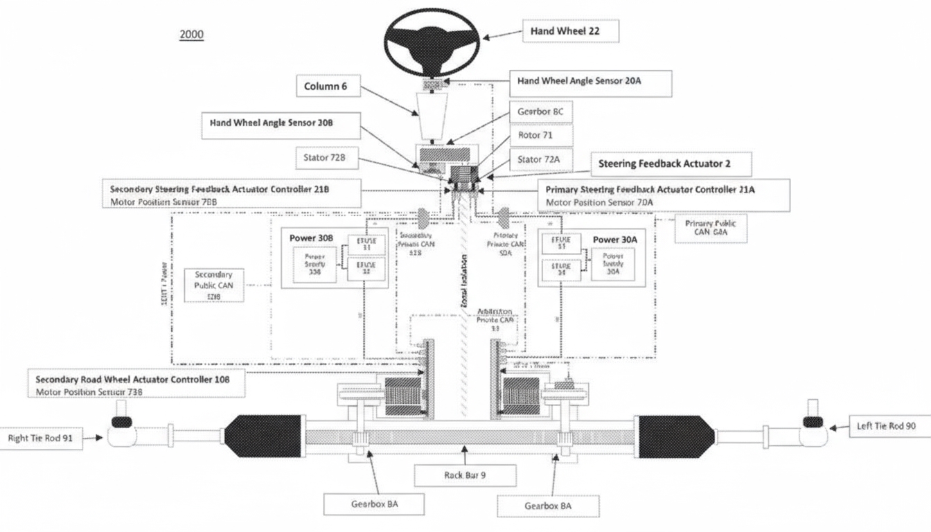
The on-board charger (OBC) is a power electronics device in electric vehicles (EVs) that charges the traction battery. It converts 220V AC to high-voltage DC, ensuring reliable vehicle operation. The OBC includes protective features such as overvoltage, undervoltage, overcurrent, and undercurrent safeguards, cutting off power during system anomalies.
Internal Structure
The OBC consists of three main components: the main circuit, the control circuit, and the wiring harness with standard parts.
Conversion Principle
The OBC processes 220V AC through an EMI filter, rectifies it to DC via an AC-DC converter, and boosts the voltage using a power factor correction (PFC) circuit. The DC is then sent to a switch and transformer for frequency conversion and voltage step-up. After a second rectification and filtering stage via an LLC circuit, the OBC outputs high-voltage DC to charge the traction battery. The initial rectification yields 310V DC, which requires two stages of boosting to meet battery requirements.
Main Circuit
The main circuit is divided into two stages:
- Power Factor Correction (PFC) Module: Enhances input power factor and suppresses high-order harmonics, improving energy efficiency by aligning voltage and current phase/frequency.
- DC-DC Converter (LLC Module): Meets battery charging voltage and current requirements while providing electrical isolation.
Control Circuit
The control circuit manages signal reception and charging operations using sensors, an electronic control unit (ECU), and IGBT drivers. It controls MOSFET switching, communicates with the battery management system (BMS), monitors OBC status, and performs handshake protocols with the charging station.
Wiring Harness and Standard Parts
The wiring harness and standard components connect the main and control circuits, securing circuit boards and other components in place.
OBC Indicator Lights
- Power Indicator: Lights up when AC power is connected.
- Charging Indicator: Activates when the OBC is connected to the battery and charging begins.
- Warning Indicator: Illuminates to signal internal faults or incorrect operation.
OBC Fault Signals
Fault information is transmitted via the CAN bus, allowing identification of issues. Common faults include:
12V Low-Voltage Supply Anomaly
If the 12V module fails, the BMS and dashboard cannot wake up due to a missing wake-up signal, preventing communication with the OBC.
Diagnosis: If the battery relay does not close (no audible click) when AC power is applied, suspect a 12V issue. Check the low-voltage fuse box for the wake-up fuse and relay, and inspect OBC terminal connections for pin retraction.
Battery Voltage Out of Range
Before charging, the OBC checks the traction battery voltage. If the voltage is outside the operational range, charging is halted.
Diagnosis: Common causes include high-voltage connector pin retraction, blown high-voltage fuses, or battery voltage exceeding the OBC¡¯s working range.
Charging Station Handshake Failure
The OBC monitors the handshake signal with the charging station. If the control pilot (CC) switch is detected as open, the OBC assumes the charging plug is being removed and stops operation to prevent live disconnection, extending the charging plug¡¯s terminal lifespan.
 ALLPCB


