Types of ECU faults
Based on the location of the failure, ECU faults can be divided into two categories: ECU peripheral circuit faults and ECU internal faults.
ECU peripheral circuits include power supply circuits, sensor signal circuits, and actuator driver circuits. Peripheral circuit faults mainly refer to power supply circuit failures; if the power supply circuit is not functioning correctly, the ECU cannot operate normally.
ECU internal faults can be further divided into power supply circuit faults, output power module faults, memory faults, and faults caused by water ingress or moisture.
Power supply circuit faults
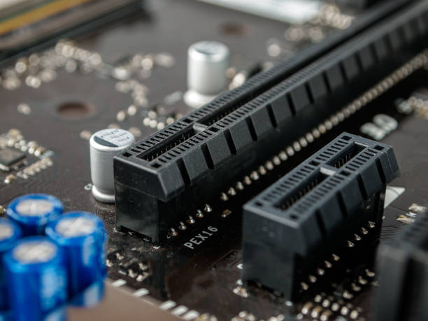
Surge voltages can cause many components to fail. The most common failures involve surface-mount capacitors, surface-mount resistors, surface-mount diodes, and protection circuits around critical ICs, sometimes burning the PCB copper traces as well. This type of failure is the most common ECU fault.
Output power module faults
Large drive currents in output power modules cause significant heating of power boards, making them one of the most failure-prone parts of the ECU. For example, when an injector stops injecting or an engine stalls suddenly, the root cause is often breakdown of the power driver circuitry.
Memory faults
Surge voltages during operation can corrupt bytes in program memory, leading to abnormal operation of the engine or other controlled devices. After an accident, EEPROM or ROM contents can be overwritten with invalid data, causing temporary system failure.
If programmable memories (EPROM or EEPROM) are defective, they can be replaced. Use a programmer (also called a flasher) to read the program from a known-good chip, write it to a blank chip of the same model, and then install the copied chip into the ECU. Note that some manufacturers restrict the number of allowed chip copies (for example, 3–7 times) or use encryption to prevent copying.
Primary causes of ECU failures
ECU damage is usually caused by environmental factors, voltage overloads, or improper handling.
Environmental factors
Because ECUs are mounted on vehicles, they are exposed to heat, humidity, vibration, water spray, and surge voltages, which increase the likelihood of failure. Rapid temperature changes can cause condensation, and condensed water will corrode the circuit board. Water ingress can cause short circuits and irreversible corrosion.
Voltage overloads
Voltage overloads are often caused by short circuits in solenoids or actuator circuits. If a shorted solenoid or actuator is not found and fixed before replacing the ECU, the overload that damaged the original ECU may also damage the replacement. Therefore, the cause of the original ECU failure must be fully diagnosed before installing a new ECU.
Improper handling
Examples of improper handling include failing to use electrostatic discharge protection during disassembly, not disconnecting the vehicle battery before installing the ECU, or measuring ECU terminals with a low-resistance ohmmeter. These improper operations can cause ECU damage.
Fault detection procedures
When an ECU is malfunctioning, first check whether the ECU peripheral circuits are normal, then follow static and dynamic diagnostic procedures.
Check peripheral circuits
Before suspecting an internal ECU fault, confirm that peripheral circuits, especially the power supply circuits, are functioning correctly. Power supply circuit diagnosis: terminals connected directly to the battery positive via a fuse are permanent power terminals; terminals connected to the battery positive via the ignition switch or a relay are switched power terminals. Use a multimeter (for example, an AS200 multimeter) to measure the voltages at these terminals, which should equal the battery voltage. Also check that the ECU ground terminals have good continuity.
Static diagnostics
Static diagnostics use a diagnostic tool to test communication with the control system. If communication is normal, it indicates the ECU power, grounds, chip set, and basic functions are working. If communication fails, use a multimeter to check the ECU supply voltage, reference voltage (+5 V), and ground circuits.
If supply voltage and grounds are normal but the reference voltage is too low, there is likely a fault in the ECU power circuit or an external short on the reference line. If the reference voltage is too high, that also indicates a power circuit fault or an internal open in the power ground. If static checks are normal, proceed to dynamic data stream diagnostics.
Dynamic diagnostics
Dynamic diagnostics involve using a diagnostic tool to read live data while the system is running and observing sensor signals. If a signal is missing, disconnect the sensor and use a signal simulator to generate the appropriate input (preferably injected at the ECU input) and test again.
If simulated signals produce correct readings, the fault is in the external wiring or the sensor itself. If no data appear, inspect the connector solder joints and interface circuitry. If soldering is intact, the ECU input signal processing circuitry may be faulty. If input data are normal but outputs are faulty, perform static tests on output components one by one. Use a multimeter and a test lamp to observe results: place the multimeter before the driver circuit and the test lamp after the driver circuit. If the multimeter shows correct values but the test lamp does not light, the ECU drive circuit is faulty and may be repairable by replacing the corresponding components. If the multimeter readings are incorrect, the ECU output signal processing circuitry is faulty.
Static internal ECU inspection
After static and dynamic diagnostics confirm the ECU is basically functional, perform detailed signal analysis of each parameter. If parameters differ significantly, or if input signals and output circuits appear normal while the ECU still behaves abnormally, inspect or replace the ECU.
Repairing ECU faults
In principle, ECUs are typically replaced rather than repaired, especially when the fault involves chips or program corruption. However, some ECU faults can be repaired by replacing discrete components. Common repairable faults include the following.
Power supply faults
There are two main types of ECU power faults: main supply faults and reference voltage (5 V) faults.
1) Main supply faults: one common cause is a shorted protection diode (often caused by reverse battery connection). This can be fixed by removing or replacing the diode with one of the same specification. Another cause is an open main ground trace (burned trace), which can be repaired with soldering and jumper wiring.
2) Reference voltage faults: if the reference voltage is too low, disconnect related external circuits; if the reference voltage then returns to 5 +/- 0.1 V, the external sensor load is excessive and must be located and removed. If the reference voltage still does not reach 5 +/- 0.1 V, replace the voltage regulator module. If the reference voltage is too high (greater than 5 V), inspect the power module ground and PCB ground traces, repair the ground trace, or replace the module as needed.
Output power module faults
Locate the corresponding power module and measure its input and output signal voltages. If the module is confirmed defective, replace it with an identical or equivalently specified module, such as ignition modules, HVAC control modules, fuel injector control modules, or fan control modules.
Capacitor and resistor failures
Some capacitors are electrolytic and can fail after prolonged service. Replace failed capacitors with the same capacitance and a voltage rating of 16–25 V. The same principle applies to replacing resistors.
Water ingress and moisture
If the ECU has been exposed to water or moisture, dry it before reuse. One drying method is to rinse the ECU board with anhydrous ethanol (industrial alcohol), then place the ECU in a large sealed bag connected to a vacuum pump (an HVAC vacuum pump is acceptable). Apply vacuum and keep it for 24 hours to dry, then reinstall and test.
Boards exposed to flooding may show corrosion that causes broken or bridged component leads or component damage. Components should be inspected and repaired or replaced individually. For example, a repair shop received a Cadillac with the symptom that when the headlights or other electrical devices were switched on or off during normal engine operation, the exhaust backfired, sometimes severely enough to rupture the exhaust. Peripheral circuits tested normal and there were no diagnostic trouble codes when read with the L236 diagnostic tool. Opening the ECU revealed a corroded ground conductor that had broken. This conductor was the ECU internal ground point for the oxygen sensor signal shield. With the shield ground open, the oxygen sensor signal was susceptible to interference from other electrical loads. Re-soldering the ground connection restored the shield and eliminated the fault; the vehicle returned to normal operation.
 ALLPCB


