 ALLPCB


Component placement accuracy is a critical factor in determining the quality of Surface Mount Technology (SMT) assembly. In SMT manufacturing, even a slight misalignment during component placement can lead to defects, reduced performance, or complete failure of the printed circuit board (PCB). This blog post explores how SMT component placement accuracy impacts assembly quality and dives into key practices like pick and place machine calibration, component placement optimization, automated optical inspection (AOI), and SMT assembly quality control to ensure flawless results. Whether you're an engineer or a manufacturer, understanding these elements can help elevate your production process and deliver reliable electronic products.
Why SMT Component Placement Accuracy Matters
In SMT assembly, components are mounted directly onto the surface of a PCB using automated machines. These components are often tiny, sometimes measuring less than a millimeter, and must be placed with pinpoint precision. A deviation of just 0.1 mm can cause issues like poor soldering, short circuits, or misalignment with PCB pads. According to industry data, placement errors account for up to 60% of SMT assembly defects, making accuracy a top priority for manufacturers aiming for high-quality output.
Beyond defect prevention, accurate placement ensures optimal electrical performance. Misaligned components can disrupt signal integrity, especially in high-frequency applications where impedance matching is crucial. For instance, a misaligned capacitor in a high-speed circuit might increase parasitic inductance, leading to signal delays or noise. Thus, focusing on SMT component placement accuracy directly translates to better product reliability and customer satisfaction.
How Component Placement Accuracy Affects SMT Assembly Quality
The quality of SMT assembly hinges on several factors influenced by placement accuracy. Let's break down the key areas where precision plays a vital role:
1. Soldering Quality and Defect Prevention
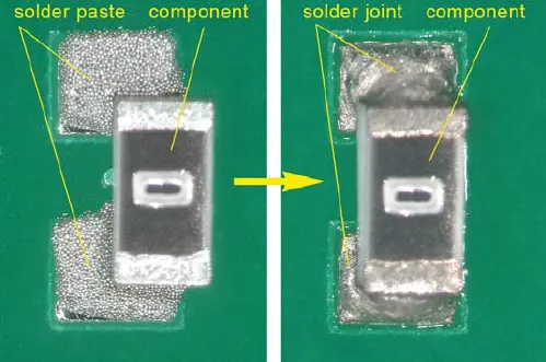
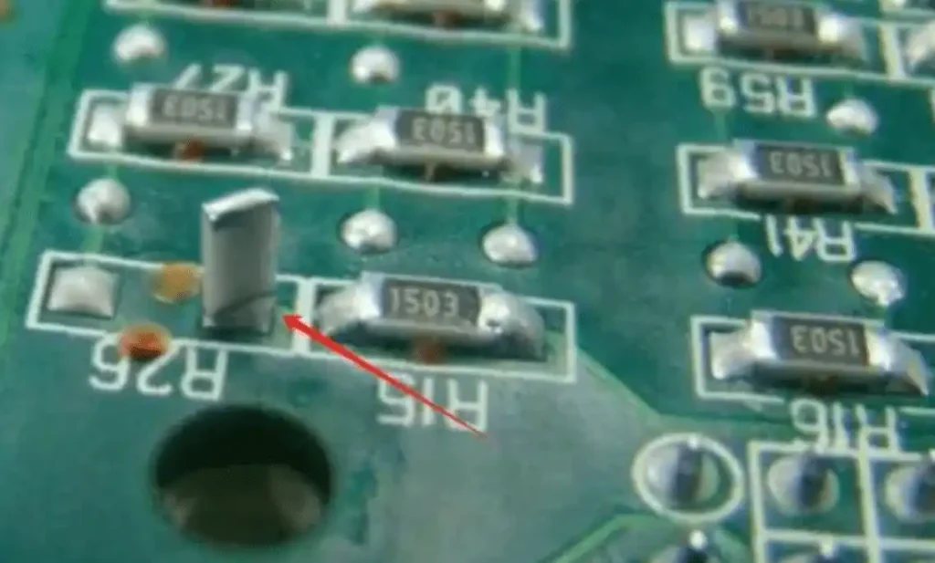
During the reflow soldering process, components must align perfectly with solder paste deposits on the PCB pads. If a component is misplaced, the solder may not form a proper joint, leading to defects like tombstoning (where one end of a component lifts off the pad) or bridging (unintended connections between pads). Studies show that misplacement by as little as 0.05 mm can increase the likelihood of soldering defects by 30%. Accurate placement ensures the solder paste bonds correctly, reducing rework costs and improving yield rates.
2. Electrical Performance and Signal Integrity
In high-speed or high-frequency circuits, component placement affects electrical characteristics like impedance and crosstalk. For example, placing a PCB decoupling capacitor too far from a power pin can introduce noise into the circuit, degrading performance. In designs operating at frequencies above 1 GHz, even a 0.2 mm deviation can alter impedance values by 5-10 ohms, disrupting signal integrity. Precision placement ensures components are positioned to meet design specifications, maintaining the intended electrical behavior.
3. Mechanical Stability and Long-Term Reliability
Misaligned components are more prone to mechanical stress during thermal cycling or vibration, common in automotive or aerospace applications. A chip resistor placed off-center might crack or detach over time, leading to circuit failure. Accurate placement enhances mechanical stability, ensuring components remain secure under varying environmental conditions and extending the product's lifespan.
The Role of Pick and Place Machine Calibration in Achieving Accuracy
Pick and place machines are the backbone of SMT assembly, capable of placing thousands of components per hour with incredible speed. However, their performance depends heavily on proper calibration. Pick and place machine calibration ensures that the machine's vision systems, nozzles, and feeders work in perfect harmony to achieve precise placement.
Key Calibration Techniques
Vision System Alignment: Modern pick and place machines use cameras to identify component shapes and PCB fiducial marks. If the vision system is misaligned, the machine may misinterpret component positions. Regular calibration of the camera system, often using test boards with known reference points, can maintain placement accuracy within 0.01 mm.
Nozzle and Feeder Checks: Nozzles pick up components from feeders and place them on the PCB. Worn or misaligned nozzles can cause placement errors. Calibrating nozzles and feeders by running test placements and measuring deviations helps maintain consistency. Some machines automatically adjust for nozzle wear, reducing errors by up to 20%.
Software Updates and Settings: The machine's software controls placement coordinates and speed. Outdated software or incorrect settings can lead to systematic errors. Updating software and verifying placement parameters before each production run ensures the machine operates at peak accuracy.
By investing time in regular calibration, manufacturers can achieve placement accuracies as tight as ±0.025 mm, significantly reducing defect rates and improving overall SMT assembly quality control.
Component Placement Optimization for Enhanced Efficiency
Beyond calibration, component placement optimization involves strategic planning and design considerations to maximize accuracy and efficiency during SMT assembly. Here are some proven methods to optimize placement:
1. Design for Manufacturability (DFM)
DFM guidelines help engineers design PCBs that are easier to assemble with minimal placement errors. For instance, ensuring adequate spacing between components prevents interference during placement. A minimum spacing of 0.3 mm between small components like 0402 resistors reduces the risk of misalignment. Additionally, placing fiducial marks at strategic locations on the PCB helps pick and place machines align accurately.
2. Component Grouping and Orientation
Grouping similar components together and aligning them in the same orientation minimizes machine head movements and reduces placement time. For example, placing all 0805 capacitors in a horizontal orientation can cut placement errors by 15% as the machine doesn't need to rotate components repeatedly. This also speeds up the assembly process, boosting throughput.
3. Feeder Setup and Component Packaging
Using high-quality feeders and ensuring components are packaged correctly (e.g., in tape and reel with minimal slack) prevents pick-up errors. A study found that improper feeder setup contributes to 25% of placement inaccuracies. Optimizing feeder positions based on component usage frequency further enhances efficiency.
By focusing on component placement optimization, manufacturers can streamline production while maintaining high accuracy standards.
Automated Optical Inspection (AOI) for Quality Assurance
Even with the best calibration and optimization, errors can still occur. This is where automated optical inspection (AOI) comes in as a critical tool for SMT assembly quality control. AOI systems use high-resolution cameras and image processing software to inspect PCBs after component placement and soldering.
How AOI Enhances Placement Accuracy
Component Position Verification: AOI checks if components are placed within acceptable tolerances (typically ±0.05 mm for position and ±1 degree for rotation). It identifies misalignments that could lead to soldering defects before they become costly issues.
Solder Joint Inspection: Post-reflow, AOI examines solder joints for defects like insufficient solder or bridging, often caused by initial placement errors. Catching these issues early prevents defective boards from reaching the final testing stage.
High-Speed Inspection: Modern AOI systems can inspect thousands of components per minute, making them ideal for high-volume production. They achieve defect detection rates of over 95%, ensuring only quality assemblies move forward.
Integrating AOI into the production line not only validates placement accuracy but also provides data for continuous process improvement. For example, if AOI detects recurring misplacements in specific areas, manufacturers can adjust machine settings or redesign the PCB layout to address the root cause.
Best Practices for SMT Assembly Quality Control
Achieving high-quality SMT assembly requires a holistic approach to SMT assembly quality control. Here are actionable best practices to ensure consistent results:
1. Implement Strict Process Monitoring
Monitor every stage of the SMT process, from solder paste printing to reflow soldering. Use real-time data from pick and place machines and AOI systems to identify trends or anomalies. For instance, if placement accuracy drops below 99.5%, it may signal the need for recalibration.
2. Conduct Regular Training for Operators
Human oversight remains essential, even with automated systems. Train operators to recognize common placement issues and perform basic machine maintenance. Well-trained staff can reduce error rates by up to 10%, according to industry reports.
3. Use Statistical Process Control (SPC)
SPC involves collecting and analyzing data to maintain process stability. By tracking placement accuracy metrics over time, manufacturers can predict potential issues before they occur. For example, a gradual increase in placement deviation might indicate nozzle wear, prompting preemptive maintenance.
4. Perform Post-Assembly Testing
After assembly, conduct in-circuit testing (ICT) and functional testing to verify that the PCB operates as intended. While AOI catches physical defects, testing ensures electrical performance aligns with design goals, closing the loop on quality control.
Conclusion: Prioritizing Accuracy for Superior SMT Assembly Quality
The impact of SMT component placement accuracy on assembly quality cannot be overstated. Precision in placement directly influences soldering quality, electrical performance, and long-term reliability of electronic products. By focusing on pick and place machine calibration, component placement optimization, and leveraging tools like automated optical inspection (AOI), manufacturers can minimize defects and maximize efficiency. Implementing robust SMT assembly quality control practices ensures that every PCB meets the highest standards, delivering value to customers and maintaining a competitive edge in the industry.
At ALLPCB, we are committed to providing cutting-edge solutions for SMT assembly, ensuring the highest levels of accuracy and quality in every project. Whether you're scaling production or prototyping a new design, prioritizing placement accuracy is the key to success.


