ALLPCB


Surface Mount Technology (SMT) assembly is a cornerstone of modern electronics manufacturing, allowing for compact, high-performance circuit boards. However, SMT assembly defects can lead to costly rework, delays, and product failures. If you're an engineer looking to identify, prevent, and fix common SMT assembly problems, you're in the right place. This guide provides a comprehensive look at SMT assembly defects identification, causes, prevention strategies, and rework techniques to ensure your production process runs smoothly.
In the sections below, we'll dive deep into the most frequent issues encountered during SMT assembly, explore their root causes, and offer practical solutions to address them. Whether you're dealing with tombstoning, solder bridges, or component misalignment, this troubleshooting guide will equip you with the knowledge to tackle these challenges head-on.
What Are SMT Assembly Defects and Why Do They Matter?
SMT assembly defects are flaws or errors that occur during the process of mounting electronic components onto a printed circuit board (PCB). These defects can compromise the functionality, reliability, and lifespan of the final product. For engineers, understanding and addressing these issues is critical because even a small defect rate—say, 1%—can translate to thousands of faulty units in high-volume production, leading to significant financial losses and damaged reputation.
Common SMT assembly problems include improper soldering, misaligned components, and insufficient solder paste. These issues often stem from design flaws, equipment malfunctions, or human error. By mastering SMT assembly defects identification and prevention, you can minimize rework costs and improve overall yield rates.
Common SMT Assembly Problems: An Overview
Before diving into specific troubleshooting techniques, let’s outline some of the most common SMT assembly problems engineers face. Recognizing these issues early is the first step toward effective resolution.
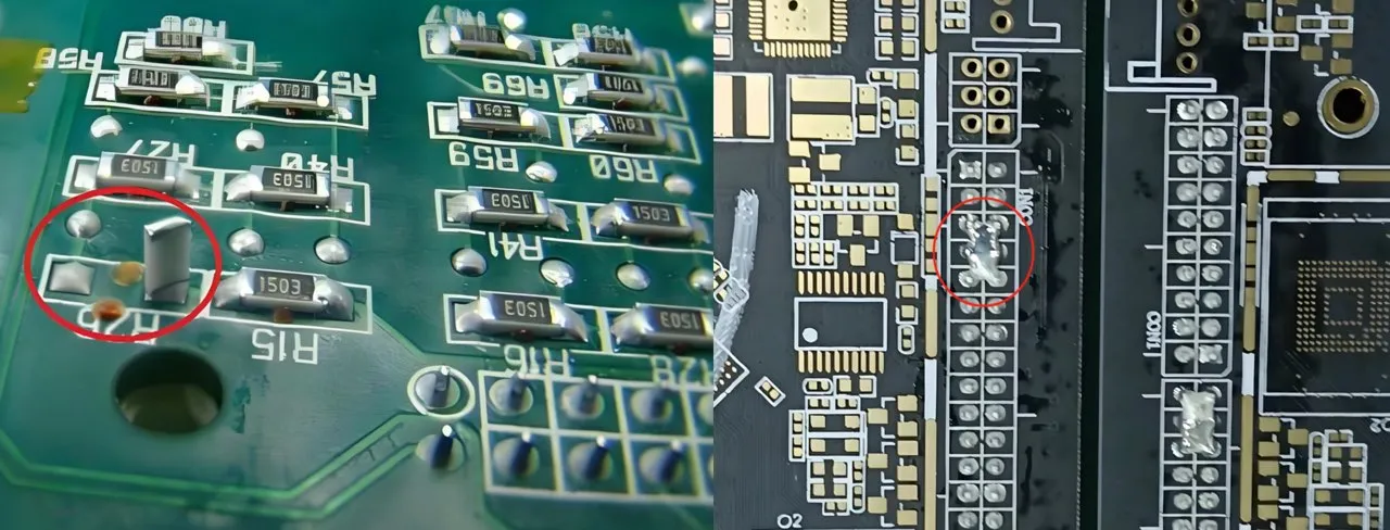
- Tombstoning: When a component stands upright on one end, resembling a tombstone, due to uneven soldering.
- Solder Bridges: Unintended connections between pads or leads caused by excess solder.
- Component Misalignment: Components placed incorrectly on the PCB, leading to poor connections.
- Insufficient Solder: Not enough solder paste applied, resulting in weak or broken joints.
- Cold Solder Joints: Poorly formed solder joints that appear dull and can cause intermittent connections.
Each of these defects has unique causes and requires specific prevention and rework techniques. Let’s explore them in detail.
SMT Assembly Defects Identification: Spotting Issues Early
Identifying SMT assembly defects early in the production process saves time and resources. Visual inspection, automated optical inspection (AOI), and X-ray inspection are among the most effective methods for detecting issues. Here’s how to spot some of the common problems:
- Tombstoning: Look for components that are lifted on one side. This is often visible to the naked eye or through AOI systems.
- Solder Bridges: Check for shiny, unintended solder connections between adjacent pads or pins, especially in fine-pitch components.
- Component Misalignment: Inspect placement accuracy using AOI or manual checks. Misaligned components may not connect properly to pads.
- Insufficient Solder: Look for joints that appear incomplete or have visible gaps. X-ray inspection can help detect hidden issues.
- Cold Solder Joints: These joints often look dull or cracked rather than shiny and smooth. They may fail under stress or vibration.
Using a combination of inspection methods ensures a higher detection rate. For instance, AOI systems can achieve defect detection rates of up to 95% for visible issues, while X-ray systems are crucial for hidden solder joint problems.
SMT Assembly Defects Causes: Understanding the Root Issues
To prevent defects, you must first understand their causes. Here are the primary reasons behind common SMT assembly problems:
1. Design-Related Causes
Poor PCB layout or pad design can lead to issues like tombstoning or misalignment. For example, if pads are too small for a component, solder may not wet evenly, causing the component to lift. Ensure pad dimensions match component specifications—typically, pad width should be 1.2 to 1.5 times the component lead width for optimal soldering.
2. Solder Paste Application Issues
Inconsistent or insufficient solder paste application often results in weak joints or insufficient solder. Stencil misalignment or clogged apertures can reduce paste volume by up to 30%, leading to defective joints. Regularly clean stencils and verify paste volume using paste inspection systems.
3. Component Placement Errors
Inaccurate placement by pick-and-place machines can cause misalignment. Machine calibration drift or incorrect feeder setup may result in placement errors as small as 0.1 mm, which is enough to disrupt fine-pitch components. Routine calibration checks are essential.
4. Reflow Soldering Problems
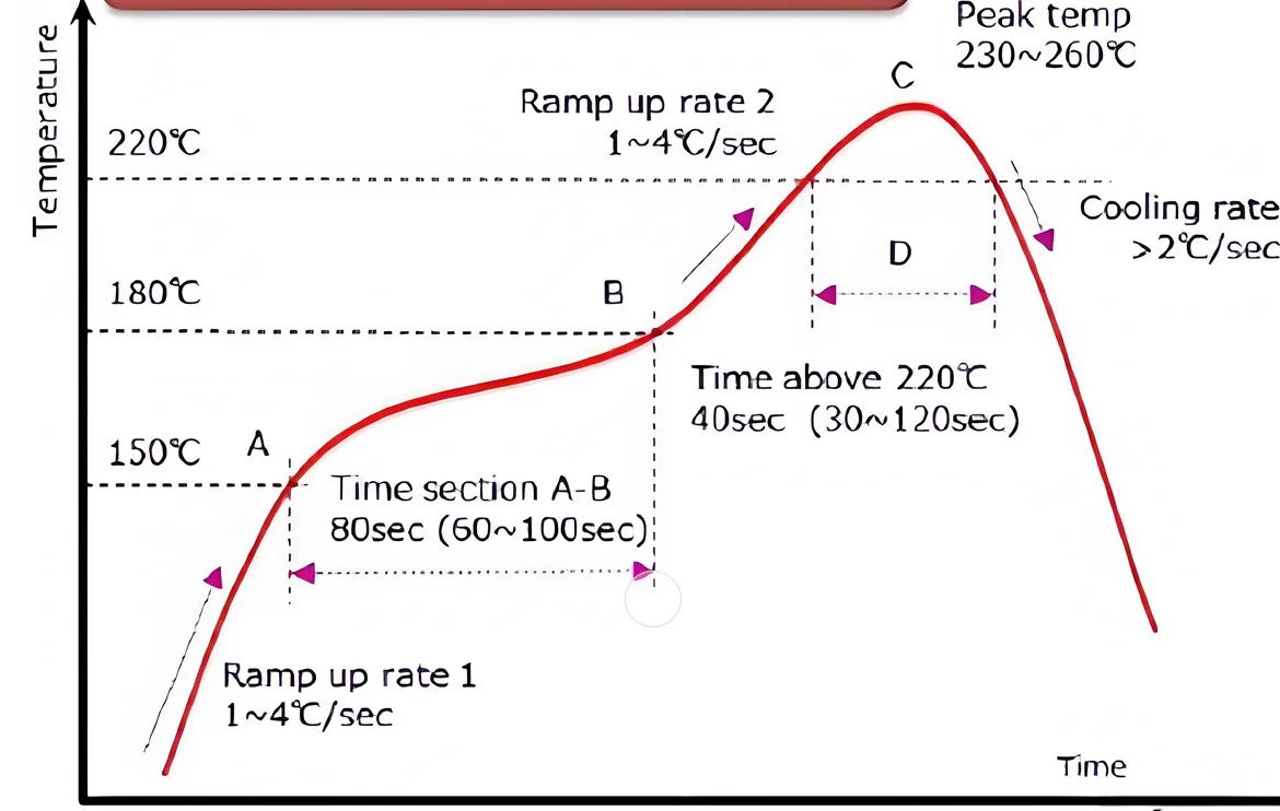
Incorrect reflow profiles can cause cold solder joints or tombstoning. If the preheat stage is too short, components may not reach the necessary temperature (typically 150-180°C) before soldering, leading to uneven wetting. Monitor and adjust reflow profiles based on board and component requirements.
5. Environmental Factors
Humidity and temperature fluctuations in the assembly environment can affect solder paste performance. High humidity (above 60%) can cause paste to absorb moisture, reducing its effectiveness. Maintain controlled conditions to avoid such issues.
SMT Assembly Defects Prevention: Best Practices for Engineers
Preventing SMT assembly defects is more cost-effective than rework. Here are actionable strategies to minimize common problems:
1. Optimize PCB Design
Start with a design that supports reliable assembly. Use design-for-manufacturing (DFM) guidelines to ensure pad sizes, spacing, and thermal balance are appropriate. For instance, equalizing pad sizes on both ends of a component can prevent tombstoning by ensuring even solder wetting.
2. Use Quality Materials
Invest in high-quality solder paste and components. Low-quality paste may have inconsistent viscosity, leading to uneven application. Check paste specifications for particle size (typically Type 3 or 4 for fine-pitch applications) and storage conditions (usually 2-10°C).
3. Calibrate Equipment Regularly
Ensure pick-and-place machines, stencil printers, and reflow ovens are calibrated. A placement accuracy of ±0.025 mm is achievable with well-maintained equipment, significantly reducing misalignment risks.
4. Implement Process Controls
Use statistical process control (SPC) to monitor variables like solder paste volume and reflow temperatures. Set control limits—such as maintaining peak reflow temperatures between 235-250°C for lead-free solder—to catch deviations early.
5. Train Personnel
Human error accounts for a significant portion of defects. Provide training on proper handling, equipment operation, and defect identification. A well-trained team can reduce error rates by up to 20%.
SMT Assembly Rework Techniques: Fixing Defects Efficiently
Even with the best prevention strategies, defects can still occur. Knowing effective SMT assembly rework techniques is essential for minimizing losses. Here’s how to address common issues:
1. Reworking Tombstoning
Use a hot air rework station to reflow the affected component. Apply flux to the pads, then heat the area to 240-260°C for lead-free solder, ensuring even wetting. Re-position the component if necessary using tweezers. Avoid excessive heat to prevent damage to nearby components.
2. Removing Solder Bridges
Use a solder wick or desoldering braid with a soldering iron set to 300-350°C to remove excess solder. Apply flux to the bridge first to facilitate solder flow into the wick. Clean the area with isopropyl alcohol to remove residue.
3. Correcting Misaligned Components
For minor misalignments, reflow the component using a hot air station to reposition it. For severe cases, remove the component entirely using desoldering tools, clean the pads, and re-place it with fresh solder paste.
4. Fixing Insufficient Solder
Add a small amount of solder to the joint using a fine-tip soldering iron. Apply flux first to ensure proper adhesion. Avoid over-applying, as excess solder can create new bridges.
5. Addressing Cold Solder Joints
Reflow the joint with a soldering iron or hot air tool, ensuring the temperature reaches the melting point of the solder (around 217°C for lead-free alloys). Add flux to improve wetting and inspect the joint for a shiny, smooth finish.
Advanced Tools and Technologies for Troubleshooting
Modern tools can significantly enhance your ability to identify and fix SMT assembly defects. Automated optical inspection (AOI) systems can scan boards at speeds of up to 100 cm2 per second, detecting issues with 99% accuracy for visible defects. X-ray inspection is invaluable for hidden solder joint issues, especially under BGA components, where defects are not visible to the naked eye.
Additionally, thermal imaging cameras can detect hot spots or uneven heating during reflow, helping to optimize profiles. Investing in such tools can reduce defect rates by up to 30% in high-volume production environments.
Case Study: Reducing Defect Rates in High-Volume Production
Consider a scenario where a manufacturer faced a 5% defect rate due to tombstoning in a batch of 10,000 units. By analyzing the reflow profile, they discovered the preheat stage was too short, causing uneven heating. Adjusting the profile to include a 120-second preheat at 150°C reduced the defect rate to below 1%. This simple change saved thousands of dollars in rework costs and improved delivery timelines.
This example highlights the importance of data-driven troubleshooting and process optimization in SMT assembly.
Conclusion: Mastering SMT Assembly for Reliable Results
SMT assembly defects can be a significant hurdle for engineers, but with the right knowledge and tools, they are manageable. By focusing on SMT assembly defects identification, understanding their causes, implementing prevention strategies, and mastering rework techniques, you can achieve higher yields and better product reliability.
Start by incorporating the best practices outlined in this guide into your workflow. Regularly inspect your processes, train your team, and leverage advanced inspection tools to stay ahead of common SMT assembly problems. With a proactive approach, you’ll minimize defects and ensure your PCBs meet the highest quality standards.