 ALLPCB


Introduction
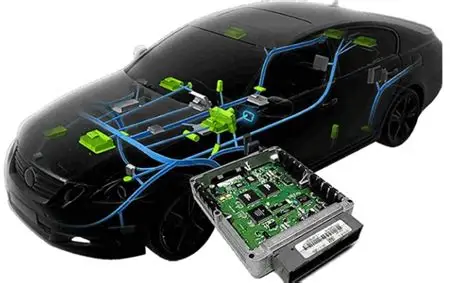
High-temperature PCBs play a critical role in applications exposed to elevated thermal conditions, such as automotive electronics, aerospace systems, and oil exploration equipment. These boards must withstand continuous operating temperatures often exceeding 150 degrees Celsius without compromising structural integrity or electrical performance. Poor PCB material selection can lead to issues like delamination, warpage, or solder joint failures, resulting in system downtime or safety risks. Engineers face the challenge of balancing thermal stability, signal integrity, and manufacturability during PCB material selection. This article explores key materials like high Tg PCBs, polyimide PCBs, and Rogers PCBs, providing factory-driven insights aligned with industry standards. Understanding these options ensures reliable performance in extreme environments.
What Are High-Temperature PCBs and Why Do They Matter?
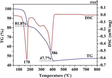
High-temperature PCBs refer to printed circuit boards designed with laminates capable of enduring prolonged exposure to heat without significant degradation. The glass transition temperature, or Tg, marks the point where the resin transitions from a glassy, rigid state to a rubbery one, typically measured using IPC-TM-650 method 2.4.25 via differential scanning calorimetry. Standard FR-4 materials have a Tg around 130 to 150 degrees Celsius, making them unsuitable for demanding thermal profiles. In contrast, high Tg PCBs exceed 170 degrees Celsius, offering better resistance to thermal cycling and lead-free soldering processes. These boards are essential in industries where components generate substantial heat or ambient conditions push limits, preventing failures that could cascade through entire systems. Factory experience shows that selecting materials based on verified Tg values directly impacts yield rates and long-term reliability.
Key Material Properties for Extreme Thermal Performance
Several properties define a material's suitability for high-temperature PCBs, starting with Tg as the primary indicator of heat resistance. Coefficient of thermal expansion (CTE) is crucial, as mismatches between layers can induce stress during temperature fluctuations, potentially causing cracks or vias failures. Decomposition temperature (Td) represents the point of significant resin breakdown, often above 300 degrees Celsius for advanced laminates. Thermal conductivity aids in heat dissipation, though high-frequency materials prioritize low dielectric constant over this trait. Moisture absorption also factors in, as absorbed water lowers effective Tg and increases delamination risk under heat. IPC-4101 specification categorizes materials via slash sheets, guiding selection for rigid and multilayer boards based on these properties.
High Tg PCBs maintain mechanical strength above 170 degrees Celsius, with Z-axis CTE typically controlled below 70 ppm per degree Celsius per IPC-4101 guidelines. Polyimide PCBs excel with Tg values over 260 degrees Celsius and low CTE across axes, ideal for flexible or rigid-flex designs in harsh settings. Rogers PCBs, often based on reinforced PTFE or hydrocarbon ceramics, provide Tg above 280 degrees Celsius alongside stable dielectric properties for RF applications. Factory testing confirms that combining these properties minimizes warpage during lamination and assembly. Engineers should request datasheets specifying these values to align with application needs.
Common Materials for High-Temperature PCBs
High Tg FR-4 variants represent an accessible upgrade from standard laminates, offering Tg from 170 to 180 degrees Celsius while retaining compatibility with conventional processes. These materials suit lead-free reflow soldering peaks around 260 degrees Celsius and moderate thermal cycling. Polyimide PCBs deliver superior performance, with continuous operation up to 250 degrees Celsius and excellent chemical resistance, making them staples in downhole drilling or avionics. Their high cost reflects advanced resin systems, but factory yields remain high with controlled curing above 200 degrees Celsius.
Rogers PCBs target high-frequency high-temperature needs, featuring low loss tangents and high thermal stability for radar or satellite systems. Hydrocarbon-based options in this family handle extreme environments with minimal signal degradation. Each material type corresponds to specific IPC-4101 slash sheets, such as those for high Tg epoxies or polyimides, ensuring standardized qualification. Practical PCB material selection weighs operating temperature against frequency requirements and board complexity.
- High Tg FR-4 — Typical Tg: 170–180°C — Key strengths: Cost-effective, process-compatible — Applications: Automotive, industrial controls
- Polyimide PCB — Typical Tg: >260°C — Key strengths: High continuous temperature, flexibility — Applications: Aerospace, oil/gas
- Rogers PCB — Typical Tg: >280°C — Key strengths: RF stability, low CTE — Applications: Telecom, defense RF
This list summarizes options for quick reference during design reviews. 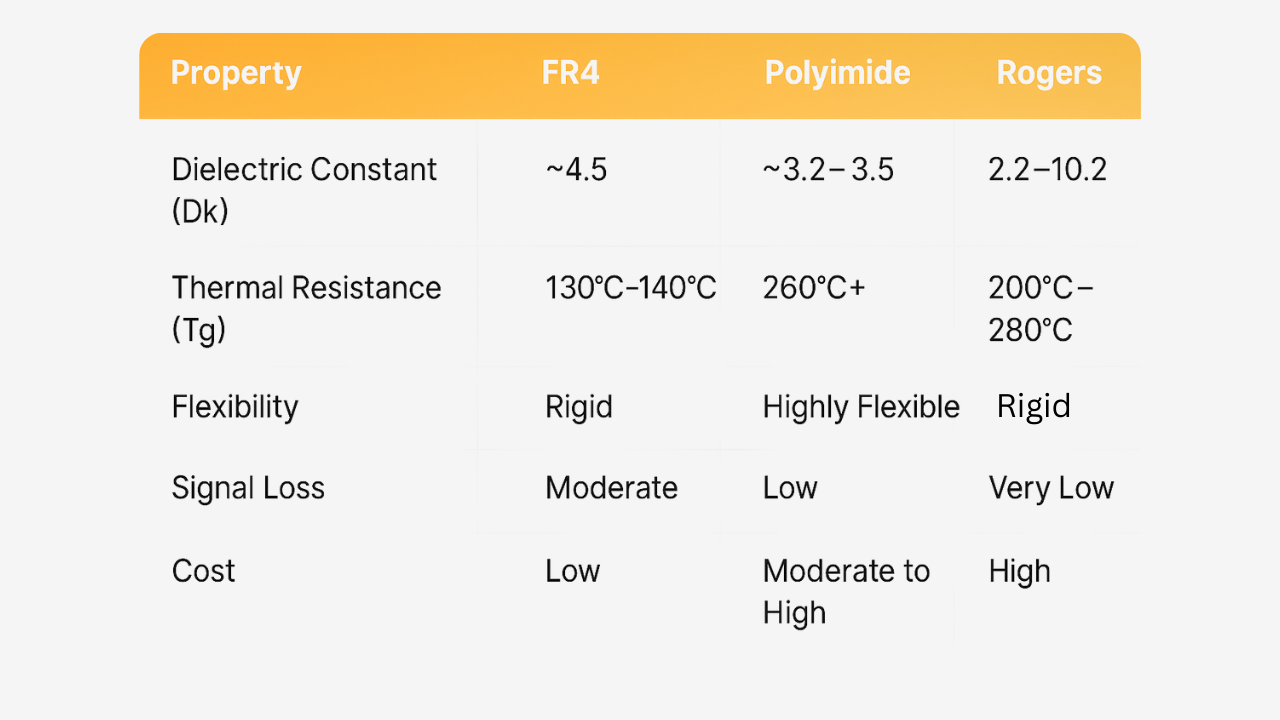
Criteria for PCB Material Selection in Extreme Environments
Effective PCB material selection begins with defining the maximum operating temperature and excursion peaks from the system requirements. For continuous exposure above 200 degrees Celsius, polyimide PCBs or Rogers PCBs outperform high Tg options. Thermal cycling profiles, including ramp rates and dwell times, demand low CTE materials to avoid fatigue. Signal integrity considerations favor Rogers PCBs for GHz frequencies due to consistent dielectric constant over temperature.
Assembly processes influence choices, as high Tg PCBs support standard SMT lines while polyimides require specialized handling to prevent blistering. Cost analysis includes not just raw material but also yield impacts from warpage or drill smear. Compliance with IPC-6012 performance specifications verifies multilayer integrity under thermal stress. Factory data indicates pre-screening laminates via time-to-delamination tests per IPC-TM-650 2.4.24.1 optimizes outcomes.
Multilayer stacks amplify risks, necessitating matched CTE across cores and prepregs. Environmental factors like humidity or vibration compound thermal effects, prioritizing low moisture absorption materials. Prototyping with thermal simulations refines selection before full production.
Best Practices for Manufacturing High-Temperature PCBs
Manufacturing high-temperature PCBs demands precise control from material incoming inspection through final test. Verify Tg and CTE via IPC-TM-650 methods on incoming laminates to reject substandard lots. Lamination cycles for polyimide PCBs involve gradual ramps to 200 degrees Celsius or higher for full cure, minimizing voids. Plasma cleaning enhances adhesion in Rogers PCBs, reducing peel strength failures.
Solder mask and surface finishes must match base material thermal ratings to prevent cracking during reflow. Bake-out procedures remove moisture prior to assembly, critical for high Tg PCBs. In-circuit testing under elevated temperatures simulates end-use conditions. Factory protocols aligned with IPC-6012 ensure class 3/A qualification for high-reliability boards.
Post-process inspections focus on warpage, using dial gauges or shadow moire per IPC-TM-650 2.4.22. Rework margins narrow with advanced materials, so design for testability from the start.
Applications and Real-World Insights
In automotive underhood electronics, high Tg PCBs handle 150 degrees Celsius ambient plus component hotspots. Aerospace power supplies leverage polyimide PCBs for 200 degrees Celsius operation amid vibration. RF modules in defense use Rogers PCBs to maintain phase stability up to 125 degrees Celsius. Downhole sensors endure 225 degrees Celsius with polyimide flex-rigid hybrids. These examples underscore tailored PCB material selection for mission-critical reliability.
Conclusion
Selecting the right materials for high-temperature PCBs hinges on understanding Tg, CTE, and process compatibility within extreme environments. High Tg PCBs offer a balanced entry point, while polyimide PCBs and Rogers PCBs address peak demands in thermal and RF scenarios. Adhering to IPC standards guides factory-aligned decisions, enhancing yield and longevity. Engineers benefit from datasheets, simulations, and qualification testing to mitigate risks. Prioritizing these factors ensures robust performance where standard boards fail.
FAQs
Q1: What is a high Tg PCB, and when should I use one?
A1: A high Tg PCB features a glass transition temperature above 170 degrees Celsius, measured per IPC-TM-650 2.4.25, surpassing standard FR-4's 130 to 150 degrees Celsius limit. Use them in lead-free assembly or environments up to 150 degrees Celsius continuous, like industrial controls or automotive ECUs. They reduce warpage and delamination risks during thermal cycling, improving reliability without shifting to costlier exotics. Factory verification confirms suitability for class 3 assemblies.
Q2: How do polyimide PCBs compare to Rogers PCBs for high-temperature applications?
A2: Polyimide PCBs excel in continuous temperatures over 250 degrees Celsius with high mechanical strength, ideal for flexible designs in oil exploration. Rogers PCBs prioritize RF performance with low loss and high Tg stability, suiting high-frequency telecom and defense systems. Polyimides offer better chemical resistance, while Rogers materials provide superior signal integrity. Select based on frequency needs and rigidity during PCB material selection; both align with IPC-4101 specifications.
Q3: What role does IPC-4101 play in high-temperature PCB material selection?
A3: IPC-4101 defines base materials for rigid and multilayer boards via slash sheets, specifying Tg, CTE, and other properties for high-temperature laminates. It standardizes qualification, ensuring consistency across suppliers. For extreme environments, reference slash sheets for high Tg or polyimide types to match application profiles. This factory-driven approach minimizes variability and supports reliable PCB material selection.
Q4: Can standard processes handle Rogers PCB manufacturing?
A4: Rogers PCBs require adjusted drilling and plating due to low resin content, but standard FR-4 lines adapt with plasma desmear and controlled etch rates. Lead-free reflow compatibility holds for most series, with Tg stability preventing warpage. Factory best practices include oxide or plasma treatments for multilayer bonding. Consult IPC-6012 for performance verification in high-temperature PCB production.
References
IPC-4101 — Specification for Base Materials for Rigid and Multilayer Printed Boards. IPC.
IPC-TM-650 2.4.25 — Glass Transition Temperature and Cure Factor by Differential Scanning Calorimetry. IPC.
IPC-6012E — Qualification and Performance Specification for Rigid Printed Boards. IPC, 2017.
IPC-TM-650 2.4.24.1 — Time to Delamination (TMA Method). IPC.


