 ALLPCB


Introduction
Making your own DIY PCB at home opens up endless possibilities for electronics projects for beginners. One key factor that hobbyists often overlook is PCB core thickness, which influences everything from board rigidity to etching results. In this experiment, you will build simple circuits on homemade PCBs using different core thicknesses to see the real-world differences. This hands-on approach helps you understand PCB fabrication at home without needing advanced equipment. By the end, you will gain insights into choosing the right materials for your next hobbyist electronics project. Get ready to etch, test, and assemble your own boards from scratch.
Understanding PCB Core Thickness and Its Importance
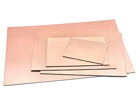
PCB core thickness refers to the dimension of the base substrate material, typically a fiberglass-reinforced epoxy like FR4 in single or double-layer boards. For DIY PCB projects, this core provides mechanical support and electrical insulation between traces. Thinner cores make boards lighter and more flexible, ideal for wearable electronics projects for beginners, while thicker ones offer greater strength for standalone circuits. However, thickness directly impacts handling during PCB etching and final assembly. Hobbyists fabricating PCBs at home must balance these traits to avoid common issues like bending or uneven results.
Why does it matter for simple circuits? A mismatched core thickness can lead to warpage after etching, making soldering tricky and reducing reliability in basic setups like LED blinkers or sensor boards. Thicker cores resist deformation better during heat exposure from soldering irons, ensuring stable connections. According to IPC-6012, qualification specifications for rigid printed boards emphasize controlled thickness to meet performance needs. This experiment reveals how variations affect your homemade PCB outcomes, helping you select optimal PCB core materials.
The Science Behind PCB Core Thickness Effects
Core thickness influences mechanical properties through the substrate's stiffness and thermal expansion. Thinner boards have lower rigidity, making them susceptible to bending under their own weight or during chemical etching processes. This can cause uneven etchant flow, leading to over-etched traces or undercuts in fine patterns. Thicker cores distribute stress more evenly, maintaining flatness crucial for precise hobbyist electronics work.
Warpage arises from asymmetric copper distribution and material shrinkage during fabrication. Industry guidelines in IPC-TM-650 outline methods to measure bow and twist, highlighting how thinner substrates amplify these defects. For instance, during PCB etching at home, heat from reactions can exacerbate bowing in slim cores, while robust thicknesses hold shape. Electrical performance also shifts slightly, as thicker dielectrics alter capacitance in simple circuits, though minimal for low-frequency beginner projects.
Material composition plays a role too. Standard PCB core materials like FR4 have consistent dielectric constants, but thickness variations affect heat dissipation. Thinner boards cool faster post-etching but may warp under soldering heat. Understanding these principles equips you to predict outcomes in your DIY PCB experiment.
Setting Up Your DIY PCB Core Thickness Experiment
Start by sourcing copper-clad boards in at least three thicknesses: a thin option for flexibility, a standard mid-range, and a thicker one for strength. These are readily available as blanks for homemade PCB fabrication. Design a simple circuit layout, such as a basic amplifier or power supply regulator, using free software to generate toner transfer masks. Print the design mirrored on glossy paper for single or double-sided transfer.
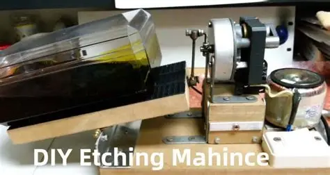
Prepare your workspace with safety gear: gloves, goggles, and ventilation for etching chemicals like ferric chloride. Clean the copper surface thoroughly with fine steel wool and acetone to ensure adhesion. Apply the toner transfer by ironing the printed mask onto the board, then etch in a plastic tray with gentle agitation. Compare etching times across thicknesses; thicker cores may require slightly longer exposure due to heat retention. After neutralizing and stripping resist, inspect for trace integrity.
Test mechanical properties post-etching. Place boards on a flat surface and measure deviation at corners with a straightedge, mimicking IPC-TM-650 bow and twist evaluation. Flex each gently to assess rigidity without cracking. Solder components like resistors and LEDs to build the circuit, noting ease of assembly.
Hands-On Testing and Observations
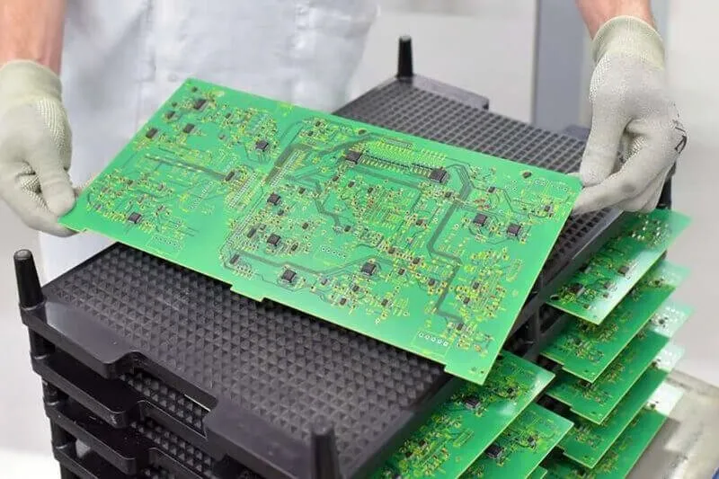
Populate each board with the same simple circuit to evaluate performance. For a blinking LED driver, thicker cores provide stable mounting for through-hole parts, resisting vibration in portable projects. Thinner ones suit surface-mount attempts but demand careful handling to prevent trace lifts. Observe warpage under heat: apply a soldering iron nearby and check for bowing, as thinner substrates deform more readily.
Strength testing involves suspending boards horizontally and adding weight at edges, qualitatively noting deflection. Thicker cores excel here, ideal for electronics projects for beginners needing durability. Etching uniformity improves with thickness due to better chemical stability, reducing undercuts on fine lines. Document results in a notebook, photographing before and after stages for your records.
Troubleshooting common issues enhances learning. If thin boards warp excessively, reinforce edges with tape during etching. Uneven etching on thick cores? Increase agitation or dilute etchant slightly. These tweaks refine your PCB fabrication at home skills.
Building and Iterating on Simple Circuits
Use your etched boards to construct practical electronics projects for beginners. A voltage divider or transistor switch demonstrates core impacts clearly. Thicker boards handle higher currents without sagging, while thin ones fit enclosures snugly. Power up and measure functionality, ensuring no shorts from warpage-induced trace proximity.
Iterate by adjusting designs: widen traces on thin cores for mechanical relief. This experiment builds intuition for future DIY PCBs, from audio amps to sensor interfaces. Hobbyist electronics thrive on such trial-and-error, aligning with standard practices for reliable outcomes.
Conclusion
Experimenting with PCB core thickness reveals critical trade-offs in rigidity, warpage, and usability for homemade PCBs. Thicker cores suit robust simple circuits, while thinner ones enable compact designs with care. By following this guide, you master PCB etching and fabrication at home, elevating your hobbyist electronics projects. Reference standards like IPC-6012 ensure your work meets professional benchmarks. Start etching today and transform ideas into functional boards.
FAQs
Q1: What is the ideal PCB core thickness for DIY PCB beginners?
A1: For electronics projects for beginners, a standard mid-thickness core balances rigidity and ease of handling during PCB etching. Thinner cores risk warpage in simple circuits, while thicker ones resist deformation better. Test a few to match your project's needs, focusing on flatness post-fabrication.
Q2: How does core thickness affect PCB etching results?
A2: Thicker PCB core materials maintain flatness during etching, promoting uniform etchant attack and cleaner traces. Thinner boards may bend, causing pooling and undercuts in homemade PCB processes. Agitate consistently and support boards to minimize issues across thicknesses.
Q3: Why do thinner DIY PCBs warp more easily?
A3: Thinner substrates have lower stiffness, amplifying stress from copper asymmetry and thermal changes in PCB fabrication at home. Standards like IPC-TM-650 quantify this bow and twist. Choose thicker cores for heat-exposed hobbyist electronics to ensure reliability.
Q4: Can I use this experiment for multilayer homemade PCBs?
A4: This focuses on single/double-layer DIY PCBs, but principles apply to cores in multilayers. Stackup thickness affects overall warpage similarly. Start simple before advancing to complex builds in your electronics projects for beginners.
References
IPC-6012 - Qualification and Performance Specification for Rigid Printed Boards. IPC.
IPC-TM-650 2.4.22 - Bow and Twist. IPC.
IPC-A-600 - Acceptability of Printed Boards. IPC.


