 ALLPCB


Introduction
Timing devices form the backbone of modern electronic circuits, ensuring precise synchronization in digital systems mounted on printed circuit boards. Electric engineers often face the decision between a crystal oscillator and a resonator when selecting components for clock generation. A crystal oscillator provides a complete, self-contained timing solution, while a resonator serves as a passive element requiring external circuitry. Understanding the crystal oscillator vs resonator debate helps optimize performance, cost, and reliability in PCB designs. This article explores their principles, trade-offs, and applications to guide informed choices.
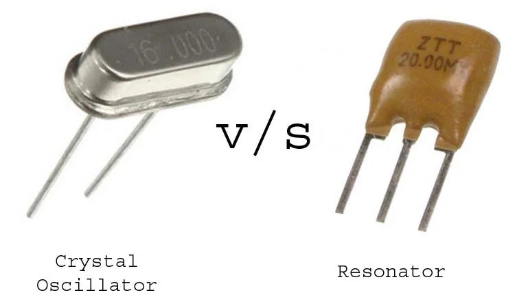
What Is a Crystal Oscillator?
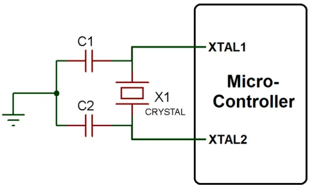
A crystal oscillator integrates a quartz crystal resonator with an internal amplifier circuit to generate a stable output signal. The quartz crystal vibrates at a precise resonant frequency when excited by an electrical field, thanks to the piezoelectric effect. This setup produces a clean sinusoidal or square wave output suitable for driving microcontrollers and logic circuits. Engineers value crystal oscillators for their ability to maintain frequency accuracy across varying conditions. In PCB layouts, these devices demand careful consideration of power supply decoupling and load capacitance matching.
The internal oscillator circuit, often based on configurations like Pierce or Colpitts, sustains oscillations without external components. This integration simplifies design but requires attention to PCB parasitics that could affect startup or stability. Crystal oscillators typically operate over a wide frequency range, supporting applications from kilohertz to megahertz.
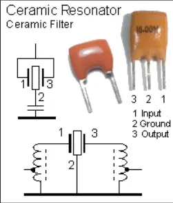
What Is a Resonator?
A resonator, commonly a ceramic resonator, functions as a passive frequency-determining element used with an external oscillator circuit in the host microcontroller or IC. It relies on the mechanical resonance of ceramic materials to set the oscillation frequency. Unlike quartz-based crystals, ceramic resonators offer built-in capacitors in three-lead packages, reducing external component count. Engineers select resonators for scenarios where ultimate precision is not critical. Their construction makes them tolerant to mechanical stress during PCB assembly processes.
Resonators generate less stable frequencies compared to quartz crystals due to material properties, but they excel in cost-sensitive designs. In practice, they pair with MCU internal oscillators, where the designer tunes the circuit for reliable startup. PCB implementation focuses on minimizing noise coupling to preserve adequate performance.
Crystal Oscillator vs Resonator: Key Differences
The core distinction in crystal oscillator vs resonator lies in their architecture and performance profiles. Crystal oscillators are active devices delivering a buffered output signal, eliminating the need for external amplification. Resonators are passive, requiring the host IC to provide the oscillation loop. Stability favors crystal oscillators, as quartz offers superior temperature and aging characteristics over ceramic materials. Size and power consumption also differ, with oscillators often larger due to integrated electronics.
Cost emerges as a pivotal factor, where resonators provide economical alternatives for less demanding timing needs. Startup time varies, with resonators typically faster due to lower Q-factor. PCB layout impacts both: crystals demand precise load capacitors and shielding, while resonators tolerate looser tolerances. Signal levels from oscillators are fixed and robust, contrasting with the variable drive from resonator-based circuits.
- Type: Crystal Oscillator — Active (integrated circuit + crystal); Resonator — Passive (ceramic or quartz element)
- Stability: Crystal Oscillator — High (quartz precision); Resonator — Moderate (material dependent)
- Cost: Crystal Oscillator — Higher; Resonator — Lower
- Size/Power: Crystal Oscillator — Larger, higher consumption; Resonator — Smaller, lower power
- PCB Complexity: Crystal Oscillator — Simplified external circuit; Resonator — Requires host IC support
Crystal Oscillator Advantages and Disadvantages
Crystal oscillators excel in delivering exceptional frequency stability, making them ideal for applications requiring tight timing margins. Their quartz core resists environmental drifts, ensuring consistent performance over temperature cycles. Engineers appreciate the plug-and-play nature, as the output drives multiple loads without buffering. Reduced sensitivity to PCB layout variations enhances reliability in high-volume production.
However, crystal oscillator disadvantages include higher upfront costs from integrated circuitry. They consume more power and generate heat, impacting battery-operated designs. Sensitivity to electrostatic discharge demands robust handling during assembly. Layout errors, such as improper grounding, can lead to oscillation failure.
Resonator Advantages and Disadvantages
Resonators shine in cost reduction and board space savings, appealing to volume-driven projects. Their ceramic construction withstands mechanical shocks better than quartz, aiding survivability in harsh assembly flows. Faster startup suits applications with frequent power cycling. Built-in capacitors streamline the bill of materials.
Resonator disadvantages center on inferior stability, leading to frequency shifts under temperature or voltage changes. This limits use in precision timing roles. External circuit tuning adds design iteration time. Noise susceptibility requires vigilant PCB routing.
Crystal Oscillator Applications
Crystal oscillator applications span high-precision domains like telecommunications and data acquisition systems. In microcontrollers for USB interfaces, they ensure compliance with strict clock tolerances. Networking equipment relies on their stability for synchronization protocols. Automotive electronics use them for engine control units where timing accuracy prevents faults.
Medical devices and instrumentation benefit from low phase noise in crystal oscillators. GPS modules demand their drift resistance for positioning accuracy. In PCB designs, they support high-speed serial buses, maintaining signal integrity across traces.
Resonator Applications
Resonator applications thrive in consumer electronics and low-end industrial controls. Simple appliances, remote controls, and toys leverage their affordability for basic timing. Battery-powered sensors use them to minimize quiescent current. Cost-sensitive IoT edge devices often employ resonators for intermittent operation.
Embedded systems with relaxed accuracy needs, such as basic motor drives, favor resonators. In mass-produced gadgets, they reduce overall BOM expenses without compromising functionality. PCB prototypes benefit from quick integration during early development phases.
Best Practices for Selecting and Implementing Timing Devices
Evaluate precision requirements first when deciding crystal oscillator vs resonator. High-stability needs point to crystal oscillators, while budget constraints favor resonators. Consider operating environment: temperature extremes suit quartz better. Power budget analysis guides the choice, balancing consumption against performance.
In PCB design, follow structured guidelines for layout. Place timing devices away from high-current paths to avoid noise injection. Implement guard traces and vias for shielding. Decoupling capacitors must match datasheet values precisely.
Assembly processes demand adherence to J-STD-020E for reflow sensitivity classification, preventing damage to moisture-sensitive crystals. IPC-A-600K criteria ensure board acceptability post-soldering. Component handling per JEDEC standards minimizes ESD risks.
Testing verifies startup reliability and frequency accuracy under load. Simulate thermal cycles to confirm stability. Iterate layouts if oscillations fail.
Conclusion
Choosing between a crystal oscillator and a resonator hinges on balancing precision, cost, and application demands. Crystal oscillators offer superior stability for critical timing, while resonators provide practical savings for tolerant designs. PCB engineers must integrate these devices thoughtfully, respecting layout and assembly standards. This crystal oscillator vs resonator analysis equips you to select optimally, enhancing system reliability.
FAQs
Q1: What are the main differences in crystal oscillator vs resonator for PCB designs?
A1: Crystal oscillators are active modules with integrated amplification for high stability, ideal for precision applications. Resonators are passive ceramic elements, cheaper but less accurate, suited for cost-sensitive uses. PCB layout for crystals requires shielding and exact capacitors, while resonators tolerate more flexibility. Stability and cost drive the choice in electric engineering projects.
Q2: What are the crystal oscillator advantages and disadvantages?
A2: Advantages include excellent frequency stability and easy integration without external circuits. Disadvantages encompass higher cost, power draw, and ESD sensitivity. In demanding applications like communications, benefits often outweigh drawbacks, and proper PCB practices can mitigate issues.
Q3: What are resonator advantages and disadvantages compared to crystal oscillators?
A3: Resonators offer low cost, small size, and good shock resistance, making them suitable for consumer goods. Disadvantages include poorer temperature stability and higher noise susceptibility. They fit non-critical timing where savings matter, provided the host IC supports the oscillator loop.
Q4: What are common crystal oscillator applications in electric engineering?
A4: They power USB, networking, and GPS systems needing precise clocks. Automotive ECUs and medical devices rely on their drift resistance. High-speed serial links also benefit from low phase noise on PCBs.
References
J-STD-020E — Moisture/Reflow Sensitivity Classification. JEDEC, 2014
IPC-A-600K — Acceptability of Printed Boards. IPC, 2020
IPC-6012E — Qualification and Performance Specification for Rigid Printed Boards. IPC, 2017


