 ALLPCB


Introduction
Flex PCB temperature sensors represent a critical advancement in flexible electronics, enabling precise temperature monitoring in confined and dynamic environments. These devices integrate sensing elements directly onto flexible substrates like polyimide, allowing them to conform to curved surfaces or move with wearable applications. Engineers designing for wearables, medical devices, and automotive systems increasingly rely on flex PCB temperature sensors for their compact form factor and reliability under mechanical stress. This guide explores the principles, design considerations, and best practices for implementing flexible temperature sensors, drawing on established engineering approaches to ensure performance and longevity. As demands for real-time flex circuit temperature measurement grow, understanding these sensors’ capabilities becomes essential for optimizing system designs.
What Are Flex PCB Temperature Sensors?
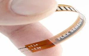
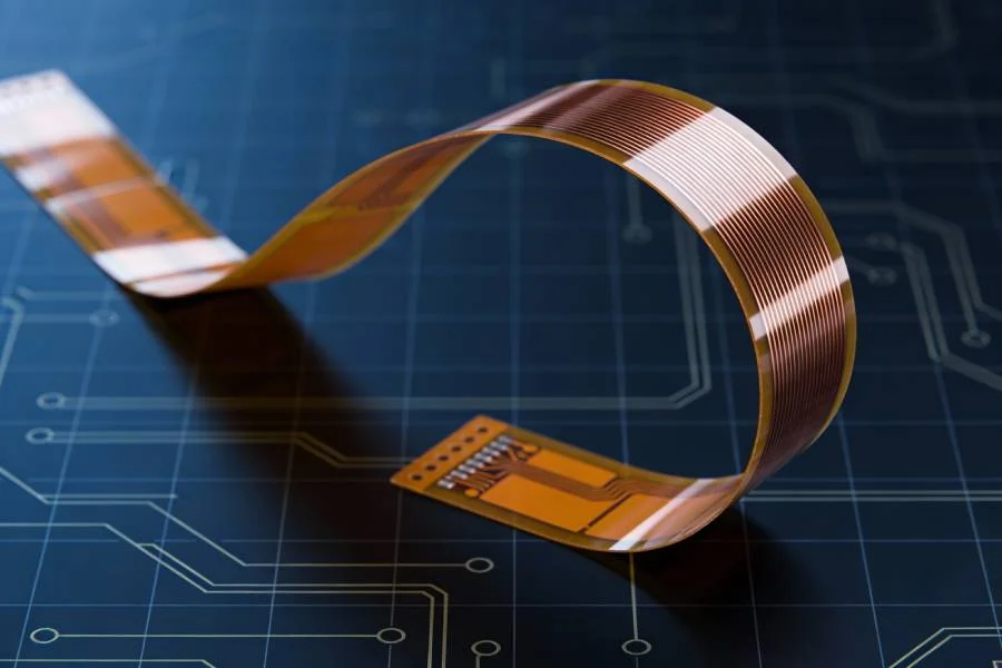
A flex PCB temperature sensor consists of a temperature-sensitive element mounted or embedded on a flexible printed circuit board, typically using polyimide as the base material for its superior thermal stability. Common configurations include surface-mount devices or thin-film sensors patterned directly onto the flex substrate, enabling seamless integration into compact assemblies. Polyimide temperature sensors excel in applications requiring flexibility, such as wearable temperature sensors that track skin or core body metrics without restricting user movement. These sensors detect changes in resistance, voltage, or current induced by temperature variations, converting them into measurable electrical signals. Unlike rigid counterparts, flex PCB temperature sensors maintain functionality through repeated bending and stretching, making them ideal for non-planar installations. Their design aligns with sectional standards like IPC-2223, which outlines parameters for flexible printed boards to ensure consistent performance.
The relevance of flexible temperature sensors stems from their ability to address limitations in traditional rigid sensors, particularly in space-constrained or mobile systems. In industries like healthcare and consumer electronics, accurate flex circuit temperature measurement supports predictive maintenance and health monitoring. For electric engineers, selecting the right sensor type involves balancing sensitivity, response time, and environmental resilience. Polyimide’s high glass transition temperature supports operation across wide ranges, typically from cryogenic lows to elevated highs, without degradation. This durability under thermal cycling underscores why flex PCB temperature sensors have become a staple in modern embedded systems.
Technical Principles of Flex PCB Temperature Sensors
Flex PCB temperature sensors operate on fundamental transduction mechanisms where temperature alters material properties, producing quantifiable outputs. Resistance Temperature Detectors (RTDs), often platinum-based thin films, exhibit linear resistance changes with temperature, offering high accuracy over wide ranges. Thermistors, either NTC or PTC variants, provide nonlinear but highly sensitive responses, suitable for narrow-range precision like body temperature tracking in wearable temperature sensors. Thermocouples generate voltage via the Seebeck effect at dissimilar metal junctions, though their integration on flex substrates requires careful junction stabilization to minimize drift. Engineers must consider substrate interactions, as polyimide’s low thermal conductivity influences heat dissipation and sensor response uniformity.
Signal conditioning circuits, routed via flex traces, amplify and linearize these outputs for microcontroller interfacing. Copper traces on polyimide flex PCBs carry minimal thermal mass, ensuring fast thermal equilibration but demanding precise layout to avoid self-heating errors. Polyimide temperature sensors leverage the material’s inherent stability, with short-term exposure limits reaching 260 degrees Celsius in demanding processes. Reliability testing per IPC-6013 qualification specifications verifies endurance through thermal shock and cycling, simulating operational stresses. These principles enable flexible temperature sensors to deliver sub-degree accuracy in dynamic conditions, critical for applications like implantable devices or aerospace monitoring.
Material selection profoundly impacts sensor performance. Polyimide films provide mechanical flexibility with tensile strength exceeding 200 MPa, resisting microcracks during flexure. Adhesive layers between copper foil and substrate must match thermal expansion coefficients to prevent delamination under temperature swings. For embedded designs, photolithography patterns platinum or nickel sensing elements directly into polyimide layers, enhancing conformal contact. This integration minimizes parasitic effects, improving signal-to-noise ratios in flex circuit temperature measurement setups.
Design Considerations for Reliable Flex PCB Temperature Sensors
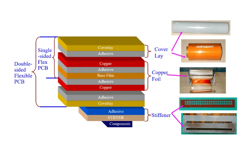
Designing a flex PCB temperature sensor begins with substrate choice, where polyimide dominates due to its balance of flexibility and thermal endurance. Trace routing follows bend radius guidelines, typically 10 times the circuit thickness, to avert fatigue in high-cycle areas. Sensor placement optimizes thermal coupling, often isolating it from power traces to reduce gradient errors. Coverlays protect against environmental factors, while stiffeners reinforce rigid-flex transitions for component mounting. Electric engineers should simulate strain distribution using finite element analysis, ensuring traces withstand millions of flex cycles without resistance drift.
Multilayer stacks incorporate ground planes for shielding electromagnetic interference, vital in noisy wearable environments. Via-in-pad configurations connect sensing elements across layers, but annular ring sizing per IPC-2223 prevents cracking. Calibration accounts for hysteresis in polymer substrates, verifying linearity post-flexure. Power delivery via thin flex traces necessitates low quiescent current sensors to avoid voltage drops. These practices yield robust flexible temperature sensors compliant with performance specs.
Assembly introduces soldering challenges, as flex materials warp under reflow heat. Low-temperature solders or conduction heating mitigate polyimide shrinkage. Post-assembly, continuity checks confirm sensor integrity before encapsulation. For harsh environments, conformal coatings enhance moisture resistance without impeding flexure.
Manufacturing and Best Practices
Manufacturing flex PCB temperature sensors demands precision lamination, etching, and testing sequences tailored to polyimide processing. Photochemical etching defines fine-pitch traces down to 25 microns, supporting dense sensor arrays. Laser drilling forms vias in multilayer flex, ensuring registration accuracy better than 50 microns. Thermal cycling tests, such as 500 cycles from -55 to 125 degrees Celsius, validate reliability without delamination or opens.
Best practices include design rule checks for annular rings and overlap margins, reducing yield losses. Controlled impedance traces stabilize RTD signals, while fiducials aid pick-and-place alignment. Bake-out removes moisture pre-lamination, preventing voids. Qualification per IPC-6013 confirms conformance across classes 2 and 3. Engineers benefit from iterative prototyping to refine sensor positioning.
Post-manufacture, environmental screening simulates end-use conditions, like vibration combined with temperature extremes. Data logging during tests quantifies drift, guiding redesigns. These steps ensure flexible temperature sensors meet application demands reliably.
Applications and Challenges
Wearable temperature sensors dominate flex PCB applications, enabling continuous skin monitoring in fitness trackers and medical patches. Automotive systems use them for battery thermal management, where flex circuits navigate tight engine compartments. Aerospace benefits from lightweight polyimide temperature sensors enduring vibration and altitude changes. Industrial IoT deploys them for predictive maintenance on curved machinery surfaces.
Challenges include signal integrity amid flexure-induced noise and thermal gradients across thin substrates. Solutions involve twisted pair routing or differential signaling for thermocouples. Humidity ingress degrades thermistors, addressed by hermetic encapsulation. Long-term drift in RTDs requires periodic recalibration algorithms. Overcoming these enhances flex circuit temperature measurement precision.
Troubleshooting Common Issues
Engineers encounter trace cracking from excessive bending, diagnosed via cross-section microscopy. Resistance shifts post-cycling signal adhesive degradation; mitigation uses higher-Tg polyimides. Sensor hysteresis appears in nonlinear thermistors, corrected by polynomial compensation. EMI coupling affects low-level thermocouple voltages, resolved with Faraday cages on flex. Systematic root-cause analysis, per J-STD-001 assembly requirements, isolates failures efficiently.
Conclusion
Flex PCB temperature sensors, powered by polyimide substrates, deliver unmatched flexibility and precision for modern electronics. From design principles to manufacturing rigor, adherence to standards like IPC-2223 and IPC-6013 ensures reliability. Electric engineers can leverage these technologies for innovative wearables and harsh-environment solutions. Key takeaways include material selection, layout optimization, and rigorous testing to maximize performance. As applications evolve, flexible temperature sensors will drive advancements in real-time monitoring.
FAQs
Q1: What materials are best for a flex PCB temperature sensor?
A1: Polyimide serves as the primary substrate for flex PCB temperature sensors due to its thermal stability up to 260 degrees Celsius short-term and mechanical flexibility. Copper foil provides conductive traces, while adhesives match CTE for reliability. Coverlay films protect against abrasion. This combination supports wearable temperature sensors in dynamic use. Design per IPC-2223 optimizes layer stackups for performance.
Q2: How do you ensure accuracy in flex circuit temperature measurement?
A2: Accuracy in flex circuit temperature measurement relies on stable sensor elements like platinum RTDs and minimal thermal mass in polyimide flex PCBs. Isolate sensors from heat sources and use ground planes for shielding. Calibrate post-flexure to account for strain effects. Thermal cycling tests verify stability over operational ranges. These steps yield sub-degree precision in flexible temperature sensors.
Q3: What temperature ranges can polyimide temperature sensors handle?
A3: Polyimide temperature sensors operate reliably from -55 degrees Celsius to over 200 degrees Celsius continuously, with peaks to 260 degrees Celsius. This suits automotive and aerospace flex PCB temperature sensors. Standards like IPC-6013 guide qualification through cycling. Material grades influence exact limits, but polyimide excels in extremes versus alternatives.
Q4: Why choose flexible temperature sensors for wearables?
A4: Flexible temperature sensors conform to body contours in wearables, enabling accurate skin monitoring without bulk. Polyimide bases resist sweat and motion, unlike rigid boards. Integration simplifies assembly, reducing failure points. They support real-time data for health apps. Reliability under flexure makes them superior for prolonged use.
References
IPC-2223C — Sectional Design Standard for Flexible/Rigid-Flex Printed Boards. IPC, 2019
IPC-6013DS — Qualification and Performance Specification for Flexible and Rigid-Flex Printed Boards. IPC, 2020
J-STD-001GS — Requirements for Soldered Electrical and Electronic Assemblies. IPC, 2020





