 ALLPCB


Introduction
Microcontroller based motor control PCBs form the backbone of precision motion systems in applications ranging from industrial automation to consumer electronics. These boards integrate a microcontroller with motor drivers, power stages, and feedback circuits to manage motors efficiently. Engineers designing such PCBs must prioritize signal integrity, thermal performance, and electromagnetic compatibility to ensure reliable operation. Key techniques like PWM motor control microcontroller implementations and PID control PCB design enable smooth speed and position regulation. This article outlines best practices drawn from established engineering principles, helping electric engineers optimize their designs for real-world demands. By following these guidelines, designers can minimize failures and enhance system efficiency.
Understanding Microcontroller Based Motor Control PCBs
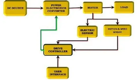
A microcontroller based motor control PCB centralizes control logic, power delivery, and sensing on a single board for motors such as BLDC or stepper types. The microcontroller processes inputs from encoders or hall sensors, computes control algorithms, and outputs signals to drivers. This integration reduces wiring complexity and latency compared to discrete components. Relevance stems from the growing need for compact, intelligent drives in robotics, electric vehicles, and HVAC systems. Proper design prevents issues like overheating or erratic motion, directly impacting product lifespan and performance. For electric engineers, mastering these PCBs means balancing computational power with robust hardware interfaces.
BLDC motor microcontroller control demands precise commutation sequences to maintain torque across speed ranges. Stepper motor microcontroller design often incorporates microstepping for smoother operation and reduced resonance. These systems rely on feedback loops to achieve closed-loop accuracy. Without optimized PCB layouts, noise can corrupt sensor signals, leading to control instability. Industry trends emphasize scalable designs that support multiple motor types via configurable firmware.
Core Technical Principles
At the heart of PWM motor control microcontroller systems lies pulse-width modulation, where duty cycle variations regulate average voltage to the motor. The microcontroller's timers generate high-frequency PWM signals, typically 10-20 kHz, to minimize audible noise and switching losses. For BLDC motors, three-phase PWM drives the inverter bridge, with phase currents synchronized to rotor position via hall sensors or back-EMF detection. Stepper motors use bipolar or unipolar PWM schemes for full-step or microstep modes, enabling fine position control without encoders in open-loop setups.
PID control PCB design implements proportional-integral-derivative algorithms in firmware to correct errors between desired and actual motor states. The proportional term responds to current deviation, integral accumulates past errors, and derivative anticipates changes. Analog feedback from current sense resistors or tachometers feeds into the microcontroller's ADC for real-time tuning. Stability requires careful gain selection to avoid oscillations, often iterated through simulation before hardware validation. Grounding strategies separate power and signal returns to prevent noise coupling into PID loops.
Motor driver circuit microcontroller integration handles high currents and voltages that exceed MCU limits. Full-bridge or half-bridge topologies using MOSFETs or IGBTs switch power based on MCU logic. Gate drive circuits provide sufficient voltage and current for fast switching, reducing shoot-through risks. Dead-time insertion in firmware prevents simultaneous conduction in complementary switches. Current limiting via sense amplifiers protects against stalls or shorts.
Best Practices for PCB Design
Start with schematic capture emphasizing modularity for easy iteration. Select microcontrollers with multiple PWM channels, high-resolution timers, and integrated peripherals like comparators for protection. Motor driver ICs should match voltage ratings and include features like overcurrent shutdown. Place decoupling capacitors close to MCU power pins to stabilize supplies during PWM transients. Follow IPC-2221 guidelines for trace width calculations based on current density to avoid excessive heating.
PCB layout demands segregated zones: digital control near the MCU, power stages isolated at the board edge, and analog sensing shielded. Use dedicated ground planes for power and signal returns, stitched with vias to minimize inductance. Route high-current paths wide and short, pairing forward and return traces to reduce loop areas for EMI suppression. Sensitive PID feedback traces should employ guard rings and avoid paralleling with switching nodes. Multi-layer boards, at least four layers, enable solid planes for better integrity.
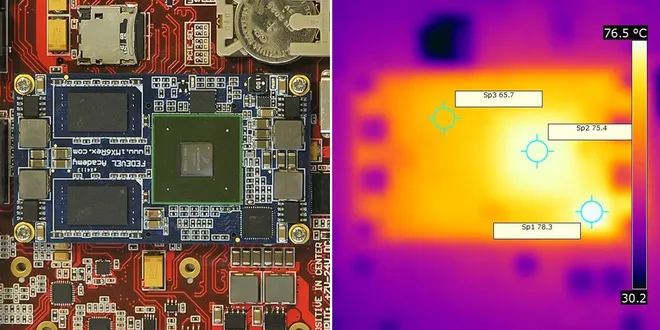
Thermal management is critical in motor driver circuit microcontroller designs, as MOSFETs generate significant heat during conduction. Calculate junction temperatures using theta-JA values and ambient conditions, incorporating copper pours and thermal vias under packages. Heatsinks or thermal pads interface with enclosures for dissipation. Simulate airflow if fans are involved. Adhere to IPC-2152 for updated current-carrying capacity charts, ensuring traces support peak motor currents without derating.
Signal integrity for PWM motor control microcontroller requires controlled rise times to limit EMI. Add snubbers across switches and ferrite beads on power lines for filtering. For high-power BLDC setups, Kelvin connections for current sensing minimize voltage drops. Bootstrapped gate drivers need sufficient capacitance to handle PWM frequencies. Test prototypes with oscilloscopes to verify clean waveforms.
Firmware-hardware synergy enhances stepper motor microcontroller design. Implement interrupt-driven control for responsive feedback. Use DMA for ADC sampling in PID loops to free CPU cycles. Calibration routines adjust for motor variances like coil resistance. Overvoltage protection diodes across phases clamp inductive spikes.
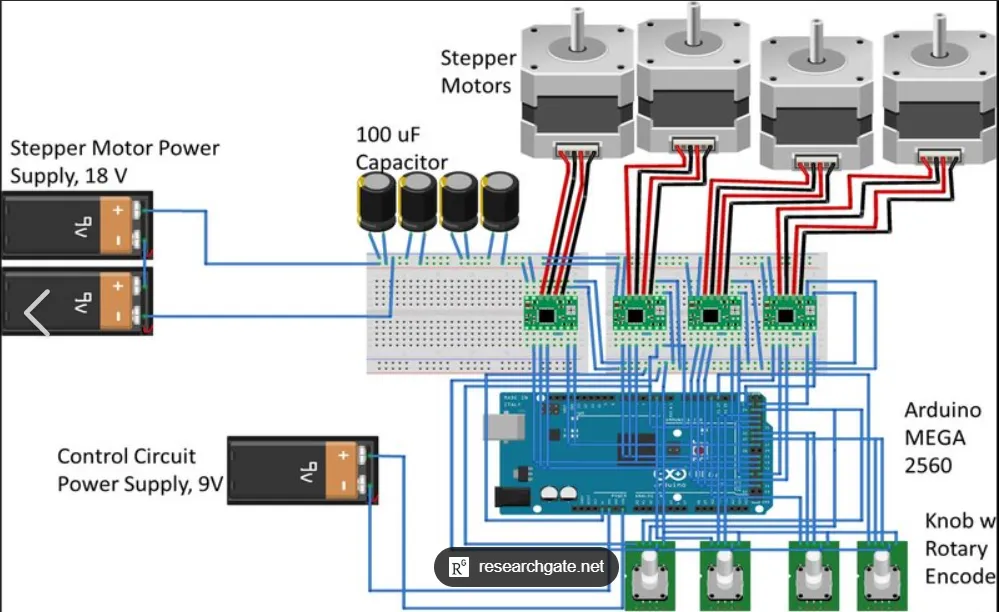
Component placement optimizes current flow: MCU central, drivers peripheral, sensors nearby. Avoid vias in high-current paths; use thicker copper if needed. Solder mask cutouts expose pads for heatsinking. Fabrication tolerances per IPC-A-600 ensure reliable plating and hole sizes for press-fit connectors.
Troubleshooting Common Design Pitfalls
Noise injection often plagues PID control PCB design, manifesting as jittery motor response. Sources include ground bounce or capacitive coupling from PWM edges. Mitigate with star grounding or single-point connections at the power entry. Oscilloscope probing isolates culprits.
Overheating in motor driver circuits arises from undersized traces or poor convection. Measure temperatures under load and iterate layouts. Insufficient gate drive causes high RDS(on) losses, spiking heat.
Bootstrapping failures in BLDC motor microcontroller control lead to uneven phases. Ensure UVLO doesn't trip during low-duty cycles. Firmware dead-time tuning prevents cross-conduction.
Vibration-induced fatigue affects stepper designs. Secure components with locking hardware and route flex-sensitive traces away from mounting holes.
Conclusion
Microcontroller based motor control PCB design demands a holistic approach integrating electrical, thermal, and layout considerations. Best practices like segregated routing, robust power delivery, and standards-compliant sizing yield reliable, efficient boards. Electric engineers benefit from iterative prototyping and simulation to refine PWM, PID, and driver implementations. These principles apply across BLDC motor microcontroller control, stepper motor microcontroller design, and beyond. Prioritizing them reduces development time and field failures, enabling innovative motion solutions.
FAQs
Q1: What are the key components in a microcontroller motor control PCB?
A1: A typical microcontroller motor control PCB includes a microcontroller with PWM timers and ADCs, motor driver bridges for power switching, current sense resistors, and feedback elements like hall sensors. Decoupling capacitors and inductors filter noise. Gate drivers amplify MCU signals for efficient MOSFET control. Proper integration ensures stable operation under varying loads.
Q2: How does PWM motor control microcontroller improve efficiency?
A2: PWM motor control microcontroller varies duty cycles to deliver precise average power, reducing average current and losses compared to linear regulation. High frequencies minimize ripple torque in BLDC motors. Synchronization with rotor position optimizes commutation. This approach enhances battery life in portable systems.
Q3: Why is PID control PCB design essential for precise motor operation?
A3: PID control PCB design provides feedback correction for speed and position accuracy in closed-loop systems. It handles disturbances like load changes via tuned gains. Analog interfaces on the PCB feed real-time data to the MCU. Stability prevents overshoot, critical for stepper and BLDC applications.
Q4: What layout tips optimize motor driver circuit microcontroller performance?
A4: Segregate power and signal grounds with planes in motor driver circuit microcontroller layouts to curb EMI. Minimize loop areas for switching currents. Place sense amplifiers near shunts. Thermal vias under drivers dissipate heat effectively.
References
IPC-2221B — Generic Standard on Printed Board Design. IPC, 2012
IPC-2152 — Standard for Determining Current Carrying Capacity in Printed Board Design. IPC, 2009
IPC-A-600K — Acceptability of Printed Boards. IPC, 2020


