 ALLPCB


Introduction
Printed circuit board repair often requires precise control over heat and component handling to restore functionality without damaging surrounding areas. Engineers working in electronics repair environments rely on specialized equipment to address issues such as damaged surface mount devices or faulty connections. A rework station provides the necessary tools for these tasks by combining controlled heating methods with accessories that support accurate component removal and replacement. Selecting appropriate equipment helps maintain assembly integrity while supporting efficient troubleshooting workflows. Logical evaluation of available options ensures that repair processes align with established engineering practices for consistent results.
What Is a Rework Station and Why It Matters
A rework station serves as a dedicated workstation for correcting defects on assembled printed circuit boards after initial manufacturing or during field service. It integrates heating elements, airflow systems, and handling tools that allow technicians to target specific components without affecting adjacent circuitry. In electronics repair settings, this equipment becomes essential when addressing failures in dense layouts where traditional methods fall short. Proper selection supports adherence to quality expectations outlined in standards such as IPC-A-610, which defines acceptability criteria for electronic assemblies. Engineers benefit from understanding these systems because they reduce the risk of secondary damage during corrective actions. The choice of station directly influences repair success rates and long-term reliability of restored boards.
Technical Principles of Rework Station Operation
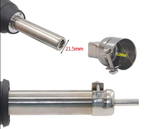
Rework stations operate through controlled application of heat and mechanical assistance to desolder or resolder components on printed circuit boards. Hot air models direct a stream of heated gas through interchangeable nozzles to raise the temperature of targeted leads or pads uniformly. This approach minimizes thermal shock compared with direct contact methods and accommodates varying component sizes through adjustable flow rates and temperatures. In contrast, a conventional soldering iron delivers localized heat via a conductive tip, which works well for through-hole parts but can struggle with fine-pitch surface mount devices due to limited heat distribution. Temperature profiling follows principles similar to those in reflow processes, where ramp rates and dwell times prevent board warpage or delamination. Engineers evaluate these mechanisms by considering thermal mass of the board and component sensitivity to ensure process parameters remain within safe limits.
Hot Air Rework Station vs Soldering Iron Comparison
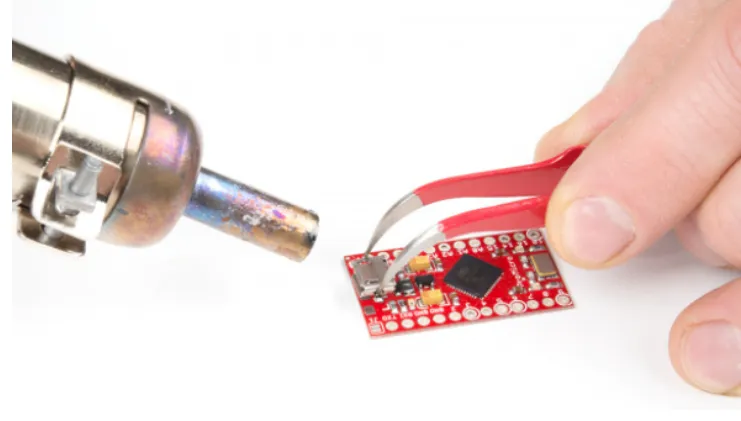
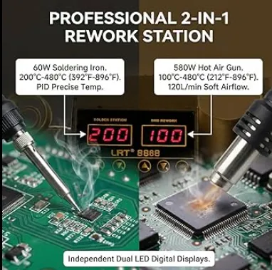
When comparing a hot air rework station to a soldering iron, the primary distinction lies in heat delivery and component accessibility. Hot air systems excel at removing or placing surface mount devices by surrounding the part with even thermal energy, reducing the chance of lifting pads or overheating neighboring elements. Soldering irons provide rapid, pinpoint energy suitable for simple joint repairs or wire attachments but require greater operator skill to avoid bridging on dense layouts. Many repair tasks benefit from stations that combine both tools, allowing seamless transitions between methods based on the specific defect. Feature considerations include nozzle variety for hot air units, tip geometry for irons, and integrated vacuum pick-up for safe component handling. Structured assessment of these differences helps engineers match equipment capabilities to the predominant repair scenarios they encounter.
Related Reading: BGA Rework Demystified: A Practical Guide to Hot Air Techniques
Key Features to Consider in a PCB Rework Station Buying Guide
A comprehensive pcb rework station buying guide begins with evaluating temperature range, airflow control, and power stability to match the thermal requirements of common board materials. Digital displays and programmable profiles enable repeatable processes that align with documented best practices for electronics repair. Additional considerations include the availability of multiple nozzle sizes, ergonomic handpieces, and safety features such as automatic cool-down cycles. For best rework station for electronics repair applications, stations offering both hot air and soldering iron functions provide flexibility across different repair types. Engineers also assess build quality, ease of calibration, and support for accessories that facilitate precise component alignment. These factors collectively determine whether a station supports efficient workflows while preserving board integrity during corrective operations.
Related Reading: Creating Custom Solder Tips: Adapting Your Iron for Unique Hand Soldering Challenges
Best Practices for Using an SMD Rework Station
Effective use of an SMD rework station starts with thorough preparation, including cleaning the work area and securing the board to prevent movement during heating. Technicians apply flux to targeted joints to promote even solder flow and reduce oxidation risks. Gradual temperature ramping followed by controlled airflow allows components to reach reflow without exceeding material tolerances. After removal or placement, cooling periods under still air help stabilize the assembly before handling. Documentation of process parameters for each board type supports consistency across multiple repairs and aids in troubleshooting recurring issues. Regular maintenance of nozzles and heating elements ensures continued performance and prevents contamination that could affect joint quality.
Conclusion
Selecting the appropriate rework station requires careful analysis of operational needs, component types, and desired process control. Engineers who apply structured evaluation criteria achieve more reliable outcomes in electronics repair tasks. Integration of both hot air and traditional soldering capabilities often provides the versatility needed for varied repair scenarios. Attention to features such as temperature precision and accessory options further enhances usability. Consistent application of these principles supports high-quality restorations while respecting the physical limits of printed circuit board materials and components.
FAQs
Q1: What should I look for in a pcb rework station buying guide when focusing on electronics repair?
A1: A thorough pcb rework station buying guide emphasizes temperature stability, interchangeable nozzles, and integrated vacuum assistance for safe component handling. Engineers evaluate power output and control interfaces to ensure compatibility with typical board sizes and component densities encountered in repair work. Additional factors include ergonomic design and calibration options that maintain process repeatability over extended use.
Q2: How does the best rework station for electronics repair differ from basic soldering tools?
A2: The best rework station for electronics repair incorporates programmable heating profiles and multiple tool heads that address both surface mount and through-hole components. Unlike single-purpose irons, these stations provide uniform heat distribution through airflow, reducing risks associated with localized overheating. This capability supports more complex corrective actions while preserving surrounding circuitry integrity.
Q3: What rework station features to consider are most important for SMD rework station applications?
A3: Key rework station features to consider for SMD rework station use include adjustable airflow rates, a range of nozzle geometries, and precise temperature feedback systems. These elements allow controlled heating of fine-pitch devices without disturbing adjacent parts. Engineers also examine build quality and accessory compatibility to support consistent results across different board layouts.
Q4: When should an engineer choose a hot air rework station vs soldering iron for PCB tasks?
A4: Selection between a hot air rework station vs soldering iron depends on the component package and required heat distribution. Hot air methods suit dense surface mount arrays by delivering even thermal energy around the entire device. Soldering irons remain suitable for isolated joints or wire work where direct contact provides sufficient control without affecting nearby elements.
References
IPC-A-610H — Acceptability of Electronic Assemblies. IPC, 2020
J-STD-001H — Requirements for Soldered Electrical and Electronic Assemblies. IPC, 2020
JEDEC J-STD-020F — Moisture/Reflow Sensitivity Classification for Nonhermetic Surface Mount Devices. JEDEC, 2022


