 ALLPCB


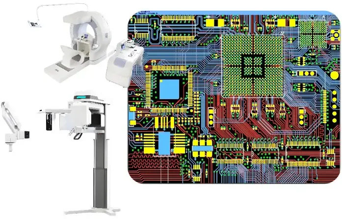
In the world of medical electronics, patient monitoring devices are critical for delivering accurate and reliable data to healthcare professionals. At the heart of these devices are printed circuit boards (PCBs) that must maintain exceptional signal integrity to ensure precise readings. Signal integrity in PCB design for medical applications is vital to avoid errors that could impact patient safety. This blog dives deep into the best practices for trace routing and grounding techniques to achieve optimal signal integrity in patient monitoring PCBs, covering key aspects like impedance control, EMI shielding, and differential signaling.
Whether you're an engineer designing circuits for medical devices or a manufacturer looking to improve PCB reliability, this guide provides actionable insights to help you navigate the challenges of high-speed, high-precision designs. Let's explore the essential strategies to ensure signal integrity in patient monitoring systems.
Why Signal Integrity Matters in Patient Monitoring PCBs
Signal integrity refers to the quality and reliability of electrical signals as they travel through a PCB. In patient monitoring devices, such as heart rate monitors, ECG machines, or blood oxygen sensors, even minor signal distortions can lead to inaccurate data, potentially endangering lives. Poor signal integrity can cause issues like noise interference, crosstalk, or signal delays, all of which compromise the performance of medical equipment.
Maintaining signal integrity in PCB design for medical applications is not just a technical requirement; it’s a matter of patient safety. These devices often operate in environments with electromagnetic interference (EMI) from other equipment, making robust design practices essential. With high-speed signals becoming more common in modern medical electronics, achieving signal integrity through proper trace routing, grounding techniques, and EMI shielding is more critical than ever.
Key Challenges in Signal Integrity for Medical PCBs
Designing PCBs for patient monitoring systems comes with unique challenges due to the sensitive nature of the signals and the strict regulatory standards in the medical field. Here are some common issues engineers face:
- High-Speed Signals: Modern patient monitoring systems often process signals at speeds exceeding 100 MHz, increasing the risk of signal degradation.
- Electromagnetic Interference (EMI): Hospitals are filled with electronic devices that can introduce EMI, disrupting signal clarity.
- Compact Designs: Medical devices are often small, forcing designers to pack components tightly, which can lead to crosstalk and noise.
- Regulatory Compliance: Medical PCBs must meet strict standards like ISO 13485, requiring designs to prioritize reliability and safety.
Addressing these challenges requires a focus on trace routing, grounding techniques, and simulation tools to predict and mitigate potential issues.
Best Practices for Trace Routing in Patient Monitoring PCBs
Trace routing is a fundamental aspect of PCB design that directly impacts signal integrity. Proper routing ensures signals travel without significant loss or interference. Below are proven strategies for optimizing trace routing in medical PCB designs.
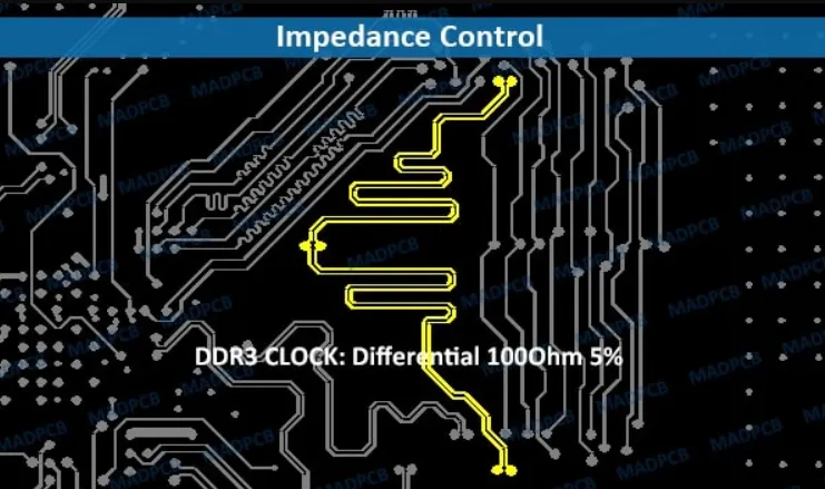
1. Implement Impedance Control in PCB Routing
Impedance control in PCB routing is crucial for maintaining signal integrity, especially in high-speed designs. Impedance mismatches can cause signal reflections, leading to data errors. For patient monitoring PCBs, target a controlled impedance of 50 ohms for single-ended traces or 100 ohms for differential pairs, as these are common standards for high-speed signals.
To achieve impedance control, calculate the trace width and spacing based on the dielectric constant of your PCB material (often around 4.5 for FR-4) and the layer stack-up. Use simulation tools to verify impedance values during the design phase. Maintaining consistent trace geometry and avoiding abrupt changes in trace width can further minimize reflections.
2. Use Differential Signaling for Noise Immunity
Differential signaling in PCB design is a powerful technique for reducing noise in patient monitoring systems. By transmitting signals over two complementary traces, differential signaling cancels out common-mode noise, which is especially beneficial in EMI-prone hospital environments.
For best results, keep differential pairs tightly coupled with equal lengths (within 5 mils of each other) to avoid timing skews. Route them away from high-noise areas, such as power lines, and maintain a consistent spacing of about 2-3 times the trace width to prevent crosstalk. This approach is ideal for critical signals like those from ECG sensors, where precision is non-negotiable.
3. Minimize Trace Lengths and Avoid Sharp Corners
Long traces can act as antennas, picking up EMI and degrading signal quality. Keep traces as short as possible, especially for high-speed signals above 50 MHz. When routing, use 45-degree angles or curved traces instead of 90-degree corners to reduce signal reflections and maintain consistent impedance.
Grounding Techniques for Optimal Signal Integrity
Effective grounding is the backbone of signal integrity in any PCB, especially for medical applications where noise must be minimized. Poor grounding can lead to ground loops, voltage differences, and increased EMI susceptibility. Here’s how to implement grounding techniques in patient monitoring PCBs.
1. Use a Solid Ground Plane
A continuous ground plane beneath signal layers provides a low-impedance return path for currents, reducing noise and EMI. Avoid splitting the ground plane unless absolutely necessary, as splits can create high-impedance paths and increase crosstalk. For multilayer PCBs, dedicate at least one layer to a solid ground plane to ensure stability.
Place vias strategically to connect components to the ground plane, keeping the path as short as possible. For high-frequency signals (above 100 MHz), place ground vias near signal vias to minimize loop inductance.
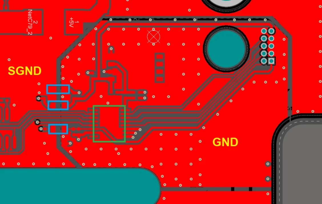
2. Separate Analog and Digital Grounds
In patient monitoring PCBs, analog signals (like sensor inputs) and digital signals (like microcontroller outputs) often coexist. Mixing these can introduce noise from digital switching into sensitive analog circuits. To prevent this, use separate ground planes for analog and digital sections, connecting them at a single point near the power supply to avoid ground loops.
This technique, often called a "star ground," ensures that noisy digital currents don’t interfere with low-level analog signals, preserving the accuracy of measurements in devices like blood pressure monitors.
3. Implement Ground Stitching for EMI Shielding
Ground stitching involves placing multiple vias around the PCB edges or near sensitive components to create a Faraday cage effect, enhancing EMI shielding for patient monitoring PCBs. This is particularly useful in environments with high EMI, as it helps contain electromagnetic fields and prevent interference with critical signals.
Space stitching vias at intervals of about 1/20th of the wavelength of the highest frequency signal (for a 100 MHz signal, this is roughly 0.15 inches or 3.8 mm apart) to effectively block EMI.
EMI Shielding Strategies for Patient Monitoring PCBs
Electromagnetic interference is a significant concern in medical environments, where multiple devices operate in close proximity. EMI shielding in patient monitoring PCBs protects sensitive signals from external noise and prevents the PCB from emitting interference that could affect other equipment.
1. Use Shielding Cans or Enclosures
Shielding cans made of conductive materials like copper or aluminum can be placed over sensitive components to block external EMI. Ensure the can is properly grounded to the PCB’s ground plane for maximum effectiveness. This is especially useful for RF-sensitive areas in patient monitoring devices.
2. Incorporate EMI Filters
Adding EMI filters, such as ferrite beads or LC filters, near power entry points can suppress high-frequency noise before it reaches critical circuits. Choose filters with a current rating matching your device’s needs (e.g., 500 mA for low-power medical sensors) and place them close to the power pins of ICs.
Leveraging Signal Integrity Simulation Tools
Before manufacturing a PCB, using signal integrity simulation tools can save time and resources by identifying potential issues early. These tools analyze factors like impedance mismatches, crosstalk, and signal delays, allowing engineers to optimize designs for patient monitoring applications.
Simulate high-speed signals at frequencies relevant to your device (e.g., 100-500 MHz for modern medical systems) to check for reflections and timing issues. Adjust trace lengths, layer stack-ups, and grounding based on simulation results to ensure reliable performance. Many design software platforms offer built-in simulation features to streamline this process.
Conclusion: Building Reliable Patient Monitoring PCBs
Ensuring signal integrity in patient monitoring PCBs is a complex but essential task for creating reliable medical devices. By focusing on impedance control in PCB routing, leveraging differential signaling, applying proper grounding techniques, and incorporating EMI shielding, engineers can design boards that deliver accurate and consistent performance. Additionally, signal integrity simulation plays a vital role in validating designs before production, reducing the risk of costly errors.
The practices outlined in this guide—such as maintaining controlled impedance, using solid ground planes, and minimizing trace lengths—provide a strong foundation for tackling the unique challenges of medical PCB design. As technology advances and patient monitoring systems become more sophisticated, staying updated on best practices for signal integrity will remain crucial for engineers and manufacturers alike.
By prioritizing these strategies, you can build PCBs that meet the stringent demands of medical applications, ensuring both patient safety and device reliability. Let’s continue pushing the boundaries of innovation in medical electronics with designs that perform flawlessly under pressure.


