 ALLPCB


Are you a hobbyist eager to dive into wearable electronics and create a basic health monitor with a DIY PCB? This guide is crafted just for you. Whether you're tracking heart rate or monitoring other vital signs, building a simple health monitor using a custom PCB is an exciting and achievable project. In this detailed blog, we’ll walk you through the steps to design and assemble an easy PCB project that brings wearable tech to life. Let’s explore the world of wearable electronics with a focus on practical, hands-on learning.
Why Build a Basic Health Monitor with a DIY PCB?
Wearable electronics are transforming how we monitor health, from smartwatches to fitness bands. For hobbyists, creating a basic health monitor offers a fantastic way to learn about PCB design, sensors, and data processing. Not only is this an easy PCB project for beginners, but it also provides real-world value by helping you understand vital signs like heart rate or temperature. With a DIY PCB, you control every aspect of the design, making it a rewarding experience that blends creativity and technical skill.
Understanding the Basics of a Simple Health Monitor
Before jumping into the design, let’s break down what a basic health monitor does. At its core, a simple health monitor measures vital signs such as heart rate or body temperature using sensors. These sensors send signals to a microcontroller, which processes the data and displays it on a screen or transmits it to another device. For a wearable device, the PCB (Printed Circuit Board) must be compact, lightweight, and power-efficient to ensure comfort and usability.
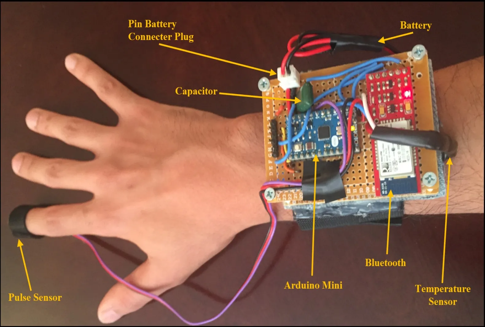
The primary components for this easy PCB project include:
- Sensors: For heart rate, a photoplethysmography (PPG) sensor can detect blood flow changes. A typical PPG sensor operates at a wavelength of around 540-570 nm for optimal signal detection.
- Microcontroller: A small, low-power unit like an Arduino-compatible board processes sensor data.
- Power Supply: A small lithium-ion battery (3.7V, 100-200mAh) powers the device.
- Display/Output: A tiny OLED screen or Bluetooth module to send data to a smartphone.
By focusing on these essentials, you can create a functional wearable health monitor without overcomplicating the design.
Step 1: Planning Your DIY PCB for Wearable Electronics
The first step in any DIY PCB project is planning. Since wearable electronics need to be small and comfortable, your PCB design should prioritize compactness and efficiency. Start by defining the purpose of your health monitor. For this guide, we’ll focus on heart rate monitoring as it’s a common and relatively simple feature to implement.
Sketch a rough layout of your components. Ensure the PCB dimensions are small—ideally under 30mm x 30mm for a wrist-worn device. Plan for minimal power consumption by choosing low-power components, as wearables often run on tiny batteries. For instance, a microcontroller with a sleep mode can reduce current draw to under 1mA when idle.
Step 2: Choosing the Right Components for Your Simple Health Monitor
Selecting components is critical for a successful easy PCB project. Here’s a breakdown of what you’ll need for a basic health monitor:
- Heart Rate Sensor: A PPG sensor module with integrated LEDs and a photodiode is ideal. These modules often output analog or digital signals at a sampling rate of 50-100Hz, sufficient for detecting heartbeats.
- Microcontroller: Opt for a compact, low-cost microcontroller with enough GPIO pins for your sensor and output. A typical choice might have a clock speed of 8-16MHz to balance performance and power use.
- Power Management: Use a small rechargeable battery and a voltage regulator to maintain a stable 3.3V or 5V supply. Ensure the regulator has a low quiescent current (under 50μA) to extend battery life.
- Output Method: A small OLED display (0.96 inches) works well for direct readings, or a Bluetooth module can transmit data wirelessly at 2.4GHz.
Keep cost and availability in mind while selecting parts, as hobbyist projects often rely on accessible components.
Step 3: Designing the PCB for Your Wearable Health Monitor
Designing a DIY PCB might sound intimidating, but with free software tools and a clear plan, it’s an achievable task for hobbyists. Follow these steps to create your PCB layout:
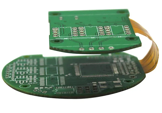
- Create a Schematic: Use design software to draw a schematic connecting your components. Place the sensor near the edge of the PCB for easy skin contact in a wearable device. Ensure signal traces from the sensor to the microcontroller are short to minimize noise—ideally under 10mm.
- Layout the PCB: Arrange components to minimize the board size. Use a two-layer PCB design for simplicity, with a ground plane on one layer to reduce interference. Keep power traces wider (around 0.5mm) to handle current without voltage drops.
- Add Mounting Points: Include holes or slots for securing the PCB in a wearable casing, ensuring it’s comfortable against the skin.
Double-check your design for errors like unconnected pins or overlapping traces before moving to production. Many hobbyists overlook trace impedance, but for analog signals from sensors, maintaining a consistent 50-ohm impedance can improve signal quality.
Step 4: Assembling Your Easy PCB Project
Once your PCB design is ready and manufactured, it’s time to assemble. Here’s how to bring your simple health monitor to life:
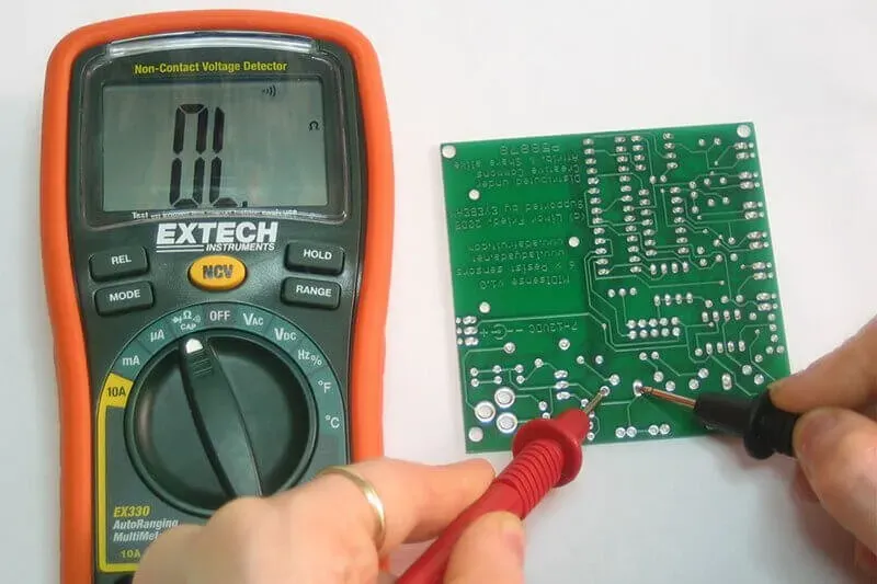
- Solder Components: Start with the smallest components like resistors and capacitors, then move to larger ones like the microcontroller and sensor. Use a soldering iron with a fine tip (1mm or smaller) and set it to 300°C for safe soldering.
- Test Connections: Use a multimeter to check for shorts or open circuits. Ensure the sensor outputs a signal (typically 0.5-1.5V for PPG sensors) when placed on the skin.
- Program the Microcontroller: Write a basic code to read sensor data and process it into a heart rate value. For a PPG sensor, filter out noise using a simple bandpass filter (0.5-5Hz) to isolate the heartbeat signal.
Assembly can take a few hours, but patience ensures a working device. If a component doesn’t work, desolder it carefully and test replacements.
Step 5: Testing and Calibrating Your Wearable Electronics
Testing is crucial to ensure your basic health monitor functions correctly. Place the sensor against your wrist or fingertip to measure heart rate. A typical resting heart rate is 60-100 beats per minute (BPM), so compare your device’s readings to a known value or a commercial monitor for accuracy.
Calibrate the sensor by adjusting thresholds in your code. For instance, if the PPG sensor signal peaks at 1.2V for a heartbeat, set a detection threshold slightly below this value (e.g., 1.0V) to avoid false readings. Log data over 5-10 minutes to check for consistency and tweak the design if readings fluctuate too much.
Step 6: Building a Wearable Enclosure
For wearable electronics, the enclosure must be comfortable and durable. Use a 3D printer or a small plastic case to create a housing for your PCB. Ensure the sensor has direct contact with the skin through a cutout in the enclosure. Secure the device with a soft strap made of silicone or fabric for all-day wear.
Keep the enclosure lightweight—under 20 grams including the PCB and battery—to avoid discomfort. Test the fit by wearing it for an hour to ensure it doesn’t irritate the skin or slip off during movement.
Tips for Success in Your DIY PCB Health Monitor Project
Here are some practical tips to make your easy PCB project smoother:
- Start Simple: Focus on one vital sign like heart rate before adding features like temperature sensing.
- Power Efficiency: Use sleep modes in your microcontroller to extend battery life to 24-48 hours on a single charge.
- Iterate: Your first design might not be perfect. Test, tweak, and redesign based on what works and what doesn’t.
- Safety First: Ensure all components are low-voltage (under 5V) to avoid any risk of electric shock in a wearable device.
Challenges to Watch Out For in Wearable Tech Projects
Building a simple health monitor isn’t without challenges. Sensor accuracy can be affected by motion or poor skin contact, leading to erratic readings. Minimize this by securing the sensor tightly against the skin and using software filters to remove noise. Battery life is another concern—wearables need to last at least a day, so optimize power usage in both hardware and code.
Lastly, PCB size constraints can make soldering tricky. If components are too close, you risk short circuits. Give yourself extra space in the layout if you’re new to soldering tiny parts.
Expanding Your Basic Health Monitor
Once your basic health monitor is working, consider adding features to enhance its functionality. Integrate a temperature sensor to track body heat, which typically ranges from 36.1°C to 37.2°C for a healthy adult. Or, add a Bluetooth module to send data to your phone for long-term tracking. Each addition will teach you more about wearable electronics and PCB design.
Keep in mind that extra features increase power draw and PCB size, so balance functionality with practicality for a wearable device.
Conclusion: Start Your Wearable Tech Journey Today
Creating a basic health monitor with a DIY PCB is an exciting way to explore wearable electronics. This easy PCB project not only teaches you about sensors, microcontrollers, and design but also results in a practical device you can use or share. From planning and designing to assembling and testing, each step builds your skills as a hobbyist.
With the steps and tips in this guide, you’re ready to build a simple health monitor tailored to your needs. Dive into the world of wearable tech and see how far your creativity can take you. Remember, every great invention starts with a small, hands-on project like this one.


