ALLPCB


Introduction
Touch panels have become increasingly common. From early military and specialized applications to widespread use today, the touch panel market has grown rapidly and diversified into multiple technologies and suppliers, which can make selection confusing for designers and engineers.
Resistive Touch Panels
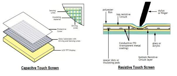
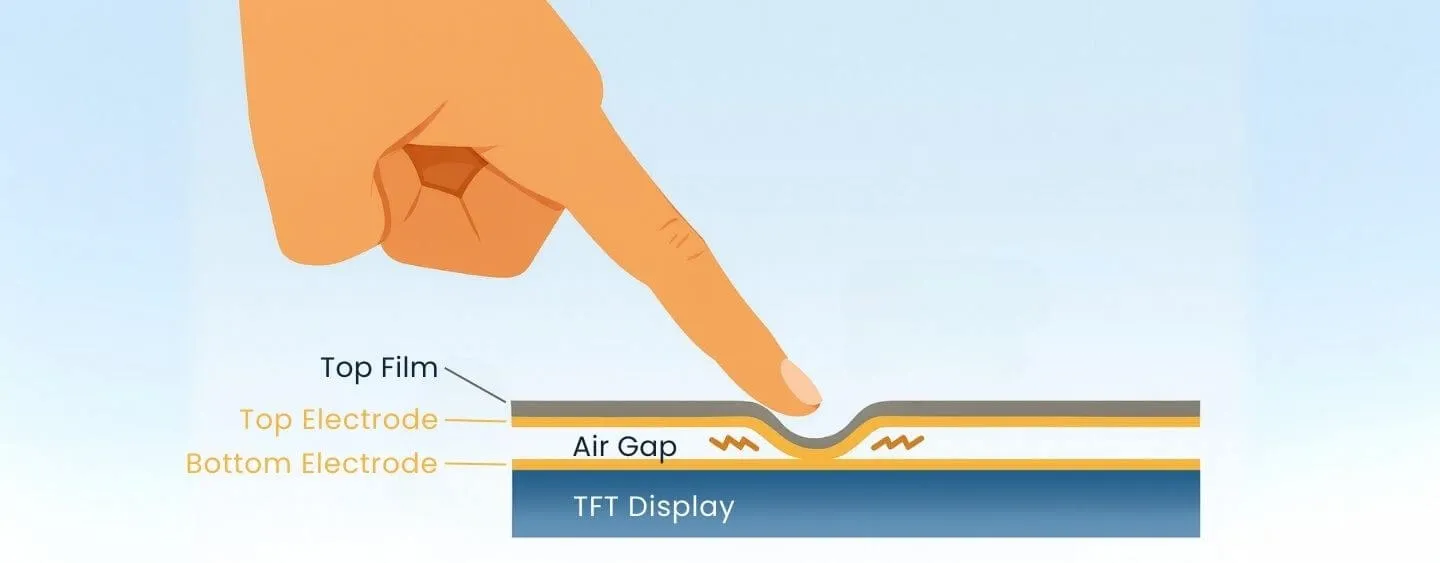
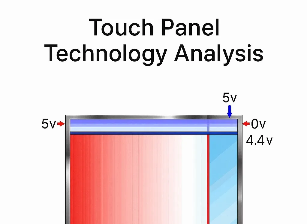
Resistive touch screens remain one of the most widely used technologies. The driving principle uses voltage division to determine coordinates. Typically, the X and Y axes are each driven by a pair of 0–5 V signals. When the screen is touched, the circuit is closed and a voltage drop occurs; the controller calculates the voltage drop ratio and derives the coordinate values.
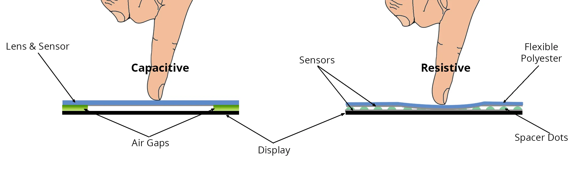
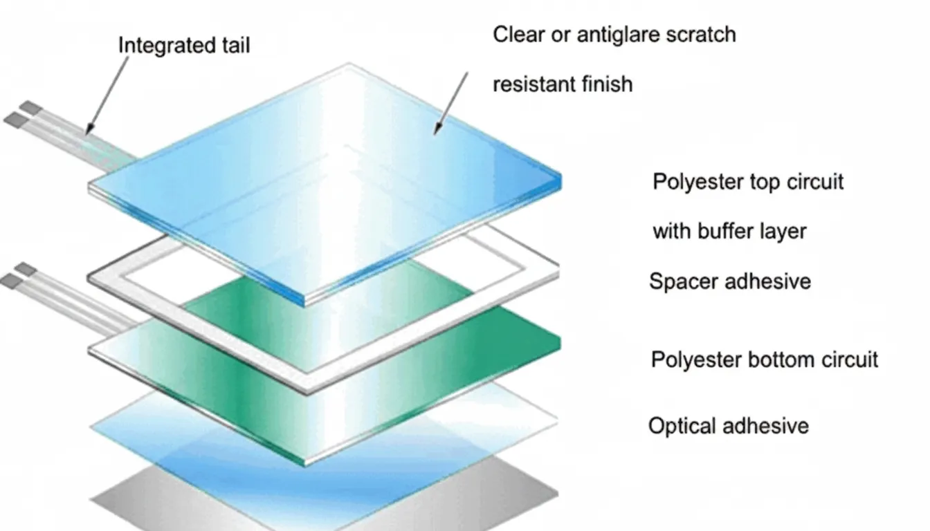
Structurally, the top layer is usually ITO-coated PET and the bottom layer is ITO-coated PET or glass. When not in use, the two layers are separated by insulating spacer dots to prevent constant-touch events at fixed points.
A common resistive architecture is Film on Glass (FG), where the top layer is ITO-coated PET and the bottom layer is ITO-coated glass. A drawback of FG is that if the glass breaks during use, shards can pose a safety hazard.
To reduce this risk, some manufacturers use a Polyester Laminated (PL) structure. In PL, the top layer is ITO-coated PET, and the stack below consists of ITO-coated PET, optical adhesive, and chemically strengthened glass. Chemically strengthened glass can withstand mechanical stress roughly 3.4 times better than ordinary glass. If the glass does fracture, the optical adhesive holds the fragments together, similar to an automotive windshield interlayer, so the panel cracks but does not shatter. This polyester-laminated design offers higher safety than Film on Glass.
Capacitive Touch Panels
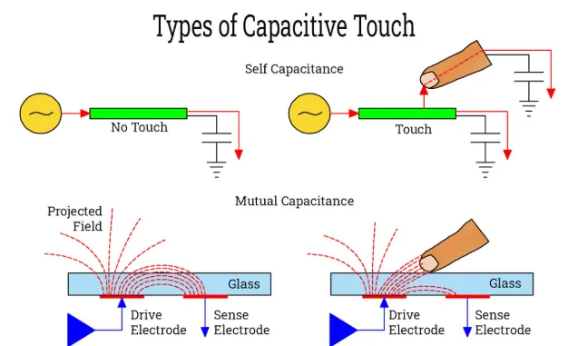
Capacitive touch panels use a different approach. Their structure is relatively simple, based on ITO glass with electrodes at the four corners to create a uniform electric field on the surface. A conductive object, such as a finger, attracts a small amount of current, and the controller computes the change to determine X and Y coordinates.
Some manufacturers have introduced advanced capacitive products such as ClearTek II. Optical and anti-glare properties are important because touch panels are typically mounted over LCDs. Achieving high transmittance and effective anti-glare performance is challenging for capacitive panels; typical transmittance is around 85%, and anti-glare effectiveness can be limited.
Certain newer capacitive designs achieve higher transmittance; for example, ClearTek II reports a transmittance of 91.5% and includes surface treatments for anti-glare and anti-reflection. Compared with resistive touch screens, capacitive panels can provide a brighter visual appearance and improved perceived image quality, which can reduce the need to increase LCD backlight brightness and potentially lower system cost.